
Introduction
Radial ground motions are in a direction perpendicular to the explosive line. The effective length (L) of the equally spaced line of charges is the number of charges multiplied by the spacing between them. Prediction methods developed are general enough to provide reasonable stress estimates over a wide range of scaled parameters. Some exceptions to the general procedures will exist as a result of explosive geometric configurations i.e. 90 degrees.
Minimum distance from the pipeline to the nearest explosive charge must be greater than two times outside pipe diameter. :A<\frac{2D}{12} \~\ B>90
A<\frac{2D}{12} \\~\\ B>90Maximum allowable angle between pipe and explosive line must be less than 90˚
S_h=\frac{PD}{2t}
S_h=\frac{PD}{2t}Where:
A − Distance from the Charge to the Pipeline(ft)
R − Equivalent Standoff Distance(ft)
B − Angle Between Pipe and Grid(deg), convert to Radians = 𝐵(0.0175)
P − MAOP−Maximum Allowable Operating Pressure(psi)
D − Pipeline Outside Diameter(in)
t − Pipe Wall Thickness(in)
Sh − Hoop Stress(psi)
R_{gc} = A + \frac{(N_1 – 1)L_1 \sin B}{2} \
R = \frac{R_{gcl}}{\cos B} \~\
L = N_1 L_1 \
W = N_1 W_1
R_{gc} = A + \frac{(N_1 - 1)L_1 \sin B}{2} \\
R = \frac{R_{gcl}}{\cos B} \\~\\
L = N_1 L_1 \\
W = N_1 W_1
Where:
L − Total Length of Explosive Line(ft)
L1 − Spacing Length Between Charges in Explosive Line(ft)
W − Total Charge Weight(lbs)
W1 − Weight of Single Charge(lbs)
N1 − Number of Charges in Explosive Line
\begin{align*}
\text{If } R > 1.5L \text{ Then } R = R_{gcg}: \
& S_c = 4.44E \left( \frac{nW}{\sqrt{(Et)(R^{2.5})}} \right)^{0.77} \
\text{If } R < 1.5L: \
& S_c = 4.44E \left( \frac{1.4n \frac{W_1}{L_1}}{\sqrt{(Et)(R^{1.5})}} \right)^{0.77}\
\text{If } S_{nc} > S_c \text{ Then } S_c = S_{nc} \
& S_{nc} = 4.44E \left( \frac{nW}{\sqrt{(Et)(R^{2.5})}} \right)^{0.77}\
&S_t=S_H+S_c\
&S=\sqrt{S_t^2-(S_tS_c)+S_c^2}
\end{align*}\
\begin{align*}
 \text{If } R > 1.5L \text{ Then } R = R_{gcg}: \\
& S_c = 4.44E \left( \frac{nW}{\sqrt{(Et)(R^{2.5})}} \right)^{0.77} \\

 \text{If } R < 1.5L: \\
& S_c = 4.44E \left( \frac{1.4n \frac{W_1}{L_1}}{\sqrt{(Et)(R^{1.5})}} \right)^{0.77}\\


 \text{If } S_{nc} > S_c \text{ Then } S_c = S_{nc} \\
& S_{nc} = 4.44E \left( \frac{nW}{\sqrt{(Et)(R^{2.5})}} \right)^{0.77}\\
&S_t=S_H+S_c\\
&S=\sqrt{S_t^2-(S_tS_c)+S_c^2}
\end{align*}\\
Where:
S𝑐 − Maximum Circumferential = S𝑙 − Maximum Longitudinal Stress(psi)
n − Equivalent Energy Release Ratio
W − Weight of Single Charge(lbs)
E − Modulus of Elasticity
t − Pipe Wall Thickness(in)
S𝑡 − Combined Hoop and Circumferential Stress(psi)
Calculated\,\%\,SMYS=\frac{S}{SMYS}100
Calculated\,\%\,SMYS=\frac{S}{SMYS}100Blasting Conditions for combined Stress Level
𝐶𝑎𝑙𝑆𝑀𝑌𝑆 >%𝑆𝑀𝑌𝑆 − NOT ACCEPTABLE/𝐶𝑎𝑙𝑆𝑀𝑌𝑆 <%𝑆𝑀𝑌𝑆 − ACCEPTABLE
Schematics
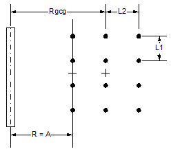
N1 – Number of Charges in Explosive Line
N2 – Number of Rows Making Up Grid
L1 – Spacing Length Between Charges in Explosive Line
L2 – Spacing Length Between Explosive Lines
W1 – Weight of Each Charge and Explosive Line
Rgcl – Distance Between Geometric Center of First Line and Pipe
R – Perpendicular Distance of the Front Explosive Line to Pipeline
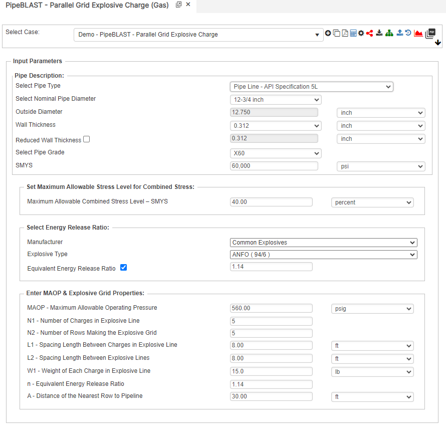
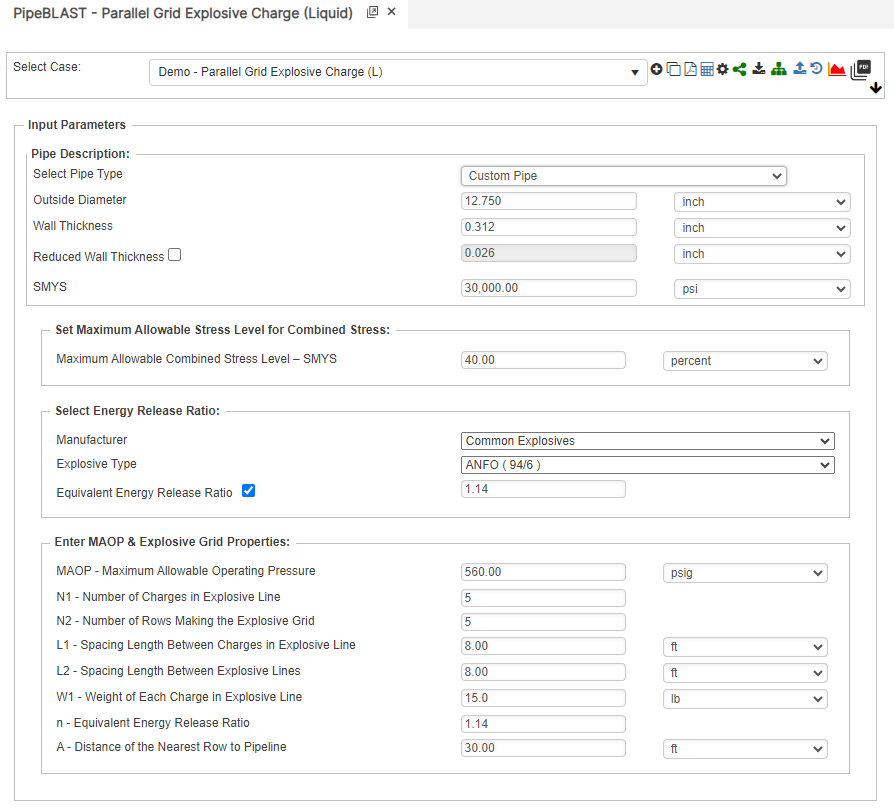
Case Guide
Part 1: Create Case
- Select the Parallel Grid Explosive Charge application from the Pipe Blast module.
- To create a new case, click the “Add Case” button
- Enter Case Name, Location, Date and any necessary notes.
- Fill out all required parameters.
- Make sure the values you are inputting are in the correct units.
- Click the CALCULATE button to overview results.
Input Parameters
- Pipe Outside Diameter
- Pipe Wall Thickness
- Specified Minimum Yield Strength
- Maximum Allowable Combined Stress Level – SMYS
- Manufacturer
- Explosive Type
- Equivalent energy release ratio
- MAOP – Maximum Allowable Operating Pressure
- N1 – Number of Charges in Front Row of Explosive Grid
- N2 – Number of Rows Making the Explosive Grid
- L1 – Spacing Length Between Charges in Explosive Line
- L2 – Spacing Length Between Explosive Lines
- W1 – Weight of Single Charge
- n – Equivalent Energy Release Ratio
- A – Distance of the Nearest Charge to Pipeline
Part 2: Outputs/Reports
- If you need to modify an input parameter, click the CALCULATE button after the change.
- To SAVE, fill out all required case details then click the SAVE button.
- To rename an existing file, click the SAVE As button. Provide all case info then click SAVE.
- To generate a REPORT, click the REPORT button.
- The user may export the Case/Report by clicking the Export to Excel icon.
- To delete a case, click the DELETE icon near the top of the widget.
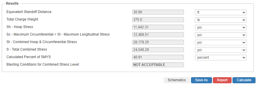
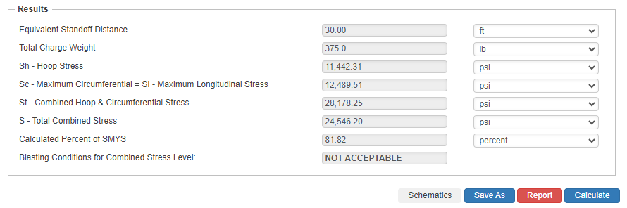
Results
- Equivalent Standoff Distance
- Total Charge Weight
- Sh – Hoop Stress
- Sc-Maximum Circumferential = Sl-Maximum Longitudinal Stress
- St – Combined Hoop && Circumferential Stress
- S – Total Combined Stress
- Calculated Percent of SMYS
- Blasting Conditions for Combined Stress Level:
References
- SWRI – Pipeline Response to Buried Explosive Detonations – Volume I
- SWRI – Pipeline Response to Buried Explosive Detonations – Volume II
- PRCI – Pipeline Response to Blasting in Rock
FAQ
-
What Are The Blasting Calculations Used Around Pipelines?
Many oil, and gas pipeline companies have minimum requirements regarding blasting around their pipeline facilities. A common blasting requirement is blasting within 200 feet or using vibratory equipment within 25 feet of a pipeline. Unfortunately, blasting take places at very close proximities due to construction and other real activities such sewer, water, cable, etc. that cause stresses to these pipelines. Check Out
-
Estimating Equivalent Release Ratio?
Most chemical explosives have close to the same energy release per unit weight (We). If the explosive being used in a blasting situation is not known, the prediction equations can be used substituting a “typical” value for (We). Check Out