
Introduction
Comparing the potential difference between an anode and cathode to the geometry factor a corrosion current can be calculated.
One limiting factor is establishing the geometry factor and measurement of the anode and cathode on the small surface of a specimen. : I = \frac{E_c – E_a}{K_a – K_c} \rho
I = \frac{E_c - E_a}{K_a - K_c} \rho
Where:
𝐼 − Corrosion current(amps)
𝜌 − Electrolyte resistivity(ohm⁄cm)
𝐸𝑐 − Potential difference between polarized cathode and a reference electrode,𝑉.
𝐸𝑎 − Potential difference between polarized cathode and the same reference electrode,𝑉.
𝐾𝑐 − Geometry factor for a cathode
𝐾𝑎 − Geometry factor for an
Case Guide
Part 1: Create Case
- Select the Ohm’s Law of Corrosion Current application from the Pipeline Corrosion list.
- To create a new case, click the “Add Case” button
- Enter Case Name, Location, Date and any necessary notes.
- Fill out all required parameters.
- Make sure the values you are inputting are in the correct units.
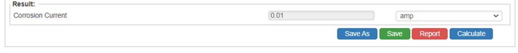
- Click the CALCULATE button to overview results.
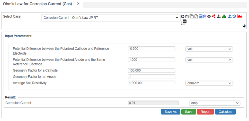
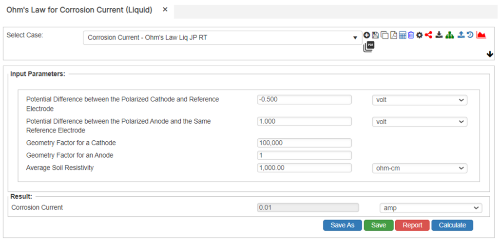
Input Parameters
- Potential Difference between the Polarized Cathode and Reference Electrode(V)
- Potential Difference between the Polarized Anode and the Same Reference Electrode(V)
- Geometry Factor for a Cathode
- Geometry Ratio for an Anode
- Average Soil Resistivity(ohm-cm)
Part 2: Outputs/Reports
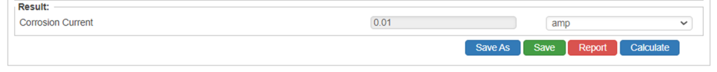
- If you need to modify an input parameter, click the CALCULATE button after the change.
- To SAVE, fill out all required case details then click the SAVE button.
- To rename an existing file, click the SAVE As button. Provide all case info then click SAVE.
- To generate a REPORT, click the REPORT button.
- The user may export the Case/Report by clicking the Export to Excel icon.
- To delete a case, click the DELETE icon near the top of the widget.
Results
- Corrosion Current(A)
References
- ANSI B31.G Calculations
- PRCI – A Modified Criterion for Evaluating the Remaining Strength of Corroded Pipe, Database for Corroded Pipe Tests and Continued Validation of RSTRENG
- NACE – Electrical Resistance and Resistivity Calculations
FAQ
-
ASME B31G Original/Modified and RSTRENG?
ASME B31.G Original and Modified (0.85) are Level 1 assessment along with most other metal loss calculations that are limited to pits and short lengths of pitting clusters. RSTRENG is a Level 2 metal loss calculation; however, it is not limited just to pits, but most lengths of pitting i.e., 2500 mm (100 inches) using interaction rules that is not uncommon on some pipelines. Check Out
-
Preventative and Corrective Measures to Control Corrosion Pitting?
A corrosion rate needed to set the re-inspection interval, reassess the performance metrics and their current applicability, plus to ensure the assumptions made are correct. At each direct examination where corrosion pitting is found, the operator should measure and record each pitting cluster. Check Out
-
Estimating Internal Corrosion Rates?
Internal corrosion is most likely to occur where water first accumulates. Predicting these locations of water accumulation serve as a method for prioritizing local examinations. Predicting where water first accumulates requires knowledge about the multiphase flow behavior in the pipe requiring certain data. Check Out
-
Estimating External Corrosion Rates?
All corrosion defects found during each direct examination should be measured, documented, and remediated as needed. At each excavation, the pipeline operator should measure and record generic environmental characteristics (such as soil resistivity, hydrology, drainage etc.). Check Out