Resistance to Earth calculations are the basis for other calculation which require the effective soil resistivity at that location. Once this value is obtained grounding charts like Dwight’s curves can be used to determine multiple anodes as required. The calculation is used in the AC Power Tool Program as a basis for a distributed anode mitigation system.
This calculation is just for a single anode which requires other calculations and or charts such as for grounding. It is the basis for other calculations such as multiple or distributed anodes.
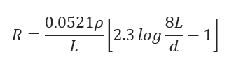
where 𝑅 — Anode resistance to earth(Ohms) 𝐿 — Anode length(ft) 𝜌 — Actual soil resitivity(Ohm/cm) 𝑑 — Anode actual diameter(ft)
Input Parameters
To create a new case, click the “Add Case” button
Select the Resistance to Earth of a Single Vertical Anode application from the Cathodic Protection module list.
Enter Case Name, Location, Date, and any necessary notes.
Fill out all required fields.
Make sure the values you are inputting are in the correct units.
Click the CALCULATE button.
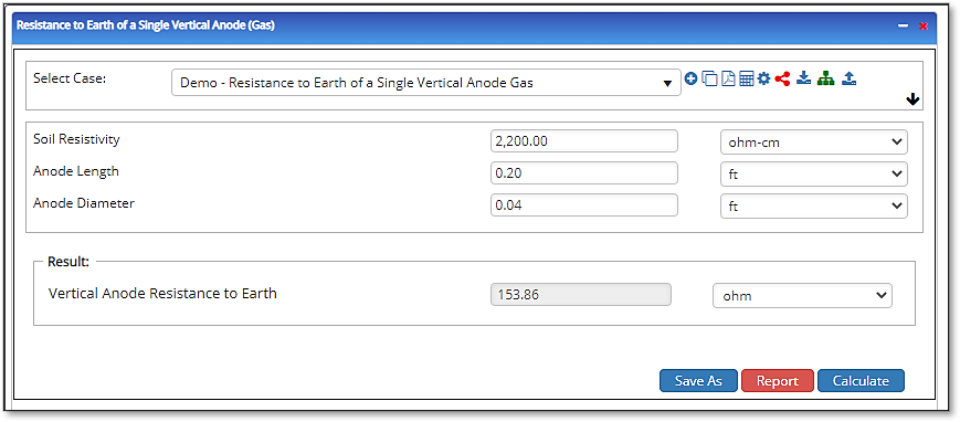
Soil Resistivity
Anode Length
Anode Diameter
Outputs/Reports
View the results.
If an input parameter needs to be edited be sure to hit the CALCULATE button after the change.
To SAVE, fill out all required case details then click the SAVE button.
To rename an existing file, click the SAVE As button. Provide all case info then click SAVE.
To generate a REPORT, click the REPORT button.
The user may export the Case/Report by clicking the Export to Excel/PowerPoint icon.
To delete a case, click the DELETE icon near the top of the widget.