
Critical Flow Behavior
If a compressible gas is expanded across a nozzle, an orifice, or the end of a pipe, its velocity and specific volume increase with decreasing downstream pressure. For a given set of upstream conditions (using the example of a nozzle), the mass rate of flow through the nozzle will increase until a limiting velocity is reached in the throat. It can be shown that the limiting velocity is the velocity of sound in the flowing media at that location. The flow rate that corresponds to the limiting velocity is known as the critical flow rate.
The absolute pressure ratio of the pressure in the throat at sonic velocity (𝑃𝑐𝑓) to inlet pressure (𝑃1) is called critical pressure ratio. (𝑃𝑐𝑓) is known as the critical flow pressure. Under critical flow conditions, the actual pressure in the throat cannot fall below the critical flow pressure even if a much lower pressure exists downstream. At critical flow, the expansion from throat pressure to downstream pressure takes place irreversibly with energy dissipated in turbulence into the surrounding fluid.
The critical flow pressure ratio in absolute units may be estimated using the ideal gas relationship in the equation below.
\frac{P_{cf}}{P_1}=\bigg[ \frac{2}{k+1} \bigg]^{\big(\frac{k}{k-1}\big)}
\frac{P_{cf}}{P_1}=\bigg[ \frac{2}{k+1} \bigg]^{\big(\frac{k}{k-1}\big)}Where:
𝑃𝑐𝑓 − Critical flow throat pressure(lb/in2)
𝑃1 = Upstream relieving pressure(lb/in2)
𝑘 − Ratio of specific heats for an ideal gas
The sizing equations for pressure relief valves in vapor or gas service fall into two general categories depending on whether the flow is critical or subcritical.
If the pressure downstream of the throat is less than or equal to the critical flow pressure, (𝑃𝑐𝑓), then critical flow will occur, and the procedures in SIZING FOR CRITICAL FLOW should be applied.
If the downstream pressure exceeds the critical pressure, (𝑃𝑐𝑓), then subcritical flow will occur, and procedure in SIZING FOR SUBCRITICAL FLOW should be applied.
A=\frac{V\sqrt{TZM}}{6.32CK_dP_1K_b}
A=\frac{V\sqrt{TZM}}{6.32CK_dP_1K_b}Where:
𝐴 − Required effective discharge area of the valve (in2)
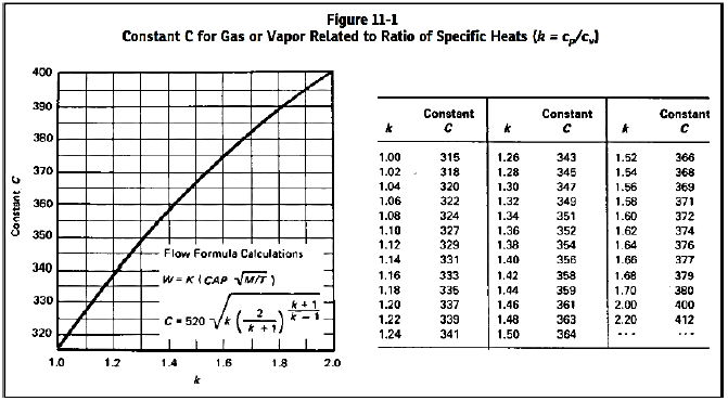
𝐶 − Coefficient determined from an expression of the ratio of the specific heats at standard conditions
𝐾𝑑 − Effective coefficient of discharge (use 0.975 for this eq.)
𝑃1 = Upstream relieving pressure (lb/in2)
𝐾𝑏 − Capacity correction factor due to back pressure
T − Relieving temperature of the inlet gas or vapor (°R)
𝑍 − Compressibility factor for the deviation of the actual gas from a perfect gas, a ratio evaluated at inlet conditions
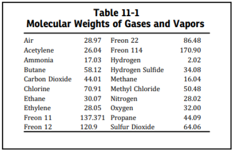
𝑀 − Molecular weight of the gas or vapor
𝑉 −Required flow through the valve (ft3/min) at 14.7
𝐺 − Specific gravity of gas referred to air=1.00 for air at 14.7 (lb/in2) absolute and 60℉
The value of the coefficient C can be evaluated from the expression of the ratio of the specific heats of the gas or vapor. The ratio of specific heats of any ideal gas and possibly the ratio of specific heats of a diatomic actual gas can be found in any acceptable reference work. When k cannot be determined, it is suggested that C = 315
When the ratio of back pressure to inlet pressure exceeds the critical pressure ratio (𝑃𝑐𝑓/𝑃1), the flow through the pressure relief valve is subcritical. This equation may be used to calculate the required effective discharge area for a conventional relief valve that has its spring setting adjusted to compensate for superimposed back pressure and for sizing a pilot-operated relief valve.
A=\frac{V}{4645F_2K_d}\sqrt{ \bigg( \frac{MTZ}{P_1(P_1-P_2)} \bigg)}
A=\frac{V}{4645F_2K_d}\sqrt{ \bigg( \frac{MTZ}{P_1(P_1-P_2)} \bigg)}Where:
𝐴 − Required effective discharge area of the valve(in2)
𝐹2 − Coefficient of subcritical flow
F_2=\sqrt{ \bigg( \frac{k}{k-1} \bigg) (r)^{2/k} \bigg[ \frac{1-r^{(k-1/k)}}{1-r} \bigg] }
F_2=\sqrt{ \bigg( \frac{k}{k-1} \bigg) (r)^{2/k} \bigg[ \frac{1-r^{(k-1/k)}}{1-r} \bigg] }𝐾𝑑 − Effective coefficient of discharge
𝑃1 = Upstream relieving pressure (lb/in2)
𝑃2 = Back pressure (lb/in2)
𝑘 − Ratio of the specific heats
T − Relieving temperature of the inlet gas or vapor (°R)
𝑍 − Compressibility factor for the deviation of the actual gas from a perfect gas, a ratio evaluated at inlet conditions
𝑀 − Molecular weight of the gas or vapor
𝑉 − Required flow through the valve(ft3/min) at 14.7
𝐺 − Specific gravity of gas referred to air=1.00 for air at 14.7 (lb/in2) absolute and 60℉
The value of the coefficient C can be evaluated from the expression of the ratio of the specific heats of the gas or vapor. The ratio of specific heats of any ideal gas and possibly the ratio of specific heats of a diatomic actual gas can be found in any acceptable reference work. When k cannot be determined, it is suggested that C = 315
Case Guide
Part 1: Create Case
- Select the Relief Valve: Sizing for Gas or Vapor application in the Facilities Module
- To create a new case, click the “Add Case” button
- Enter Case Name, Location, Date and any necessary notes.
- Fill out all required parameters.
- Make sure the values you are inputting are in the correct units.
- Click the CALCULATE button to overview results.
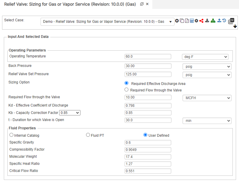
Input Parameters
- Gas or Vapor Flowing Temperature (F)
- Back Pressure (psig)
- Relief Valve Set Pressure (psig)
- Flow Rate (MSCFH)
- Relief Valve Set Pressure (psig)
- Kd – Effective Coefficient of Discharge
- Kb – Capacity Correction Factor
- Specific Gravity
- Compressibility Factor of Gas or Vapor
- Molecular Weight of Gas or Vapor
- Specific Heat Ratio
- Critical Flow Ratio
Part 2: Outputs/Reports
- If you need to modify an input parameter, click the CALCULATE button after the change.
- To SAVE, fill out all required case details then click the SAVE button.
- To rename an existing file, click the SAVE As button. Provide all case info then click SAVE.
- To generate a REPORT, click the REPORT button.
- The user may export the Case/Report by clicking the Export to Excel icon.
- To delete a case, click the DELETE icon near the top of the widget.
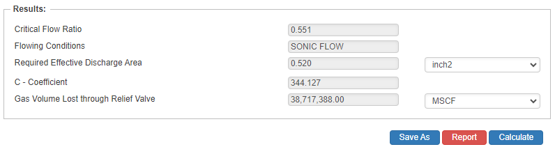
Results
- Critical Flow Ratio
- Flowing Conditions
- Required Effective Discharge Area (in2)
- C – Coefficient
- Gas Volume Lost Through Relief Valve (MSCF)
References
- ASME – Boiler and Pressure Vessel Code, Section VIII
- API – RP 520 Part 2
- ASME B31.8 Gas Transmission and Distribution Piping Systems
- ASME B31.3, B31.4 and B31.8 – Full Encirclement Sleeves (See Appendices)
Appendix
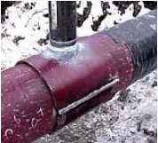
Even though Technical Toolboxes does not provide software for a full-encirclement reinforcing saddles, many operators use them to provide reinforcement for branch outlets in accordance with ASME B31.3, B31.4, B31.8 and other applicable design codes. Full-encirclement reinforcing saddles are designed to fully encircle the run pipe however; they are not designed to be pressure retaining devices. To avoid gas entrapment during welding and to prevent pressure containment, should a leak develop underneath the saddles; these saddles should be provided with a vent to allow escaping product.
A typical field applied Full Encirclement Reinforcement Weldment Saddle is shown below:

FAQ
-
Validation check: Reinforcement of Welded Branch Connection?
This table highlights the list of validation checks that are in effect in the PLTB Gas > Pipeline Facilities> Reinforcement of Welded Branch Connection – ASME B31.8 calculation. Check Out
-
Orifice Coefficient for Hot Tap Sizing?
When a compressible fluid, such as natural gas or air, is passed through an orifice, the rate of flow is determined by the area of the orifice opening; the absolute upstream pressure is 𝑃1; and the absolute downstream pressure is 𝑃2: unless the ratio 𝑃2/𝑃1. equals or is less than the critical ratio. When 𝑃2/𝑃1 equals or is less than the critical ratio downstream pressure no longer effects rate of flow through the orifice, and flow velocity at the vene contracta is equal to the speed of sound in that fluid under that set of condition. This is commonly referred to as critical or sonic flow. Orifice equations are therefore classified as “sonic” or “subsonic” equations. Check Out
-
How is Required Area calculated for Branched Weld Connection?
The calculation is using the following is the equation that we use for A3 – REQUIRED AREA
A3 = Ar – A1-A’2
where:
Ar = Reinforcement Required
A1= Reinforcement Provided
A’2 = Corrected Effective Area