
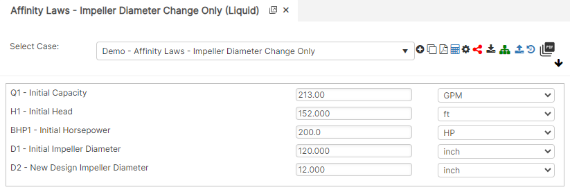
Diameter Change Only:
Impeller trimming (change) refers to the reduction of the impeller diameter, and thus a reduction of the circumferential speed at the impeller outlet of a centrifugal pump. The effect of this measure thus depends on the type of impeller. Single-vane and diagonal impellers can only be trimmed within narrow limits. Q_2 = Q_1 \left( \frac{D_2}{D_1} \right); \quad H_2 = H_1 \left( \frac{D_2}{D_1} \right)^2; \quad BHP_2 = BHP_1 \left( \frac{D_2}{D_1} \right)^3
Q_2 = Q_1 \left( \frac{D_2}{D_1} \right); \quad H_2 = H_1 \left( \frac{D_2}{D_1} \right)^2; \quad BHP_2 = BHP_1 \left( \frac{D_2}{D_1} \right)^3
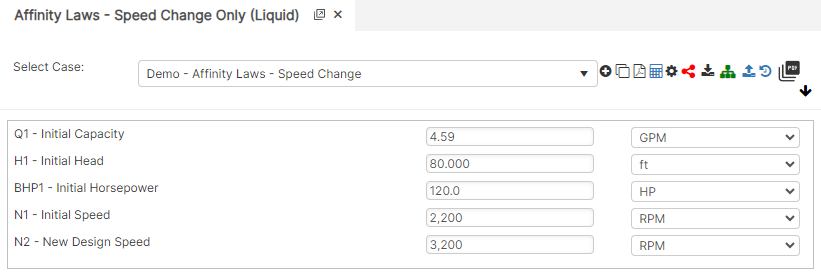
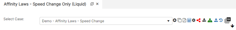
Speed Change Only:
In reciprocating pumps, the flow is not true steady-state flow, but is continually accelerating and decelerating due to the continual change in fluid velocity requires more energy, or acceleration head. Due to continual change in fluid velocity requires more energy, or acceleration head, so friction loss models may not be completely accurate when performing flow analysis. Q_2 = Q_1 \left( \frac{N_2}{N_1} \right); \quad H_2 = H_1 \left( \frac{N_2}{N_1} \right)^2; \quad BHP_2 = BHP_1 \left( \frac{N_2}{N_1} \right)^3
Q_2 = Q_1 \left( \frac{N_2}{N_1} \right); \quad H_2 = H_1 \left( \frac{N_2}{N_1} \right)^2; \quad BHP_2 = BHP_1 \left( \frac{N_2}{N_1} \right)^3
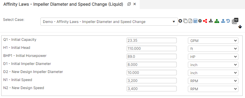
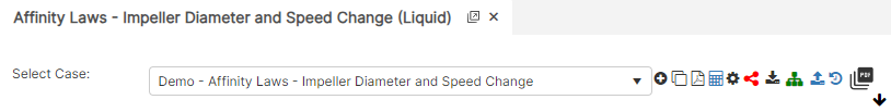
Diameter and Speed Change:
The relationship between variables involved in pump or fan performance (such as head, volumetric flow rate, shaft speed) and power. Specific speed is a term used to describe the geometry (shape) of a pump impeller. The selection of the proper pump can use this Specific Speed information to : Select the shape of the pump curve. Q_2 = Q_1 \left( \frac{D_2 N_2}{D_1 N_1} \right); \quad H_2 = H_1 \left( \frac{D_2 N_2}{D_1 N_1} \right)^2; \quad BHP_2 = BHP_1 \left( \frac{D_2 N_2}{D_1 N_1} \right)^3
Q_2 = Q_1 \left( \frac{D_2 N_2}{D_1 N_1} \right); \quad H_2 = H_1 \left( \frac{D_2 N_2}{D_1 N_1} \right)^2; \quad BHP_2 = BHP_1 \left( \frac{D_2 N_2}{D_1 N_1} \right)^3
Where:
𝐷 − Impeller Diameter (in)
𝑄 − Capacity (gpm)
𝐻 − Head (ft)
𝐵𝐻𝑃 − Brake Horsepower 𝑁−Speed (rpm)
Subscript1 for Original Conditions
Subscript2 for new Design Conditions
Case Guide
Part 1: Create Case
- Select the Affinity Laws application from the Pump Module
- To create a new case, click the “Add Case” button
- Enter Case Name, Location, Date and any necessary notes.
- Fill out all required Parameters.
- Make sure the values you are inputting are in the correct units.
- Click the CALCULATE button to overview results.
Input Parameters
- Initial Capacity (gpm)
- Initial Head (ft)
- Initial Horsepower (HP)
- Initial Impeller Diameter (in)
- New Design Impeller Diameter (in)
- Initial Speed (rpm)
- New Design Speed (rpm)
Diameter Change Only
Speed Change Only
Diameter and Speed Change Only
Part 2: Outputs/Reports
- If you need to modify an input parameter, click the CALCULATE button after the change.
- To SAVE, fill out all required case details then click the SAVE button.
- To rename an existing file, click the SAVE As button. Provide all case info then click SAVE.
- To generate a REPORT, click the REPORT button.
- The user may export the Case/Report by clicking the Export to Excel icon.
- To delete a case, click the DELETE icon near the top of the widget.
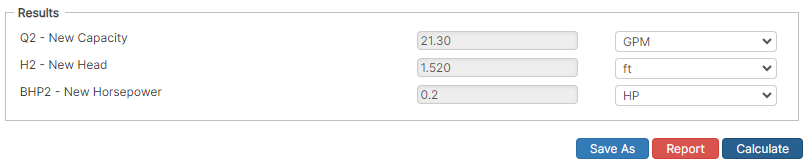
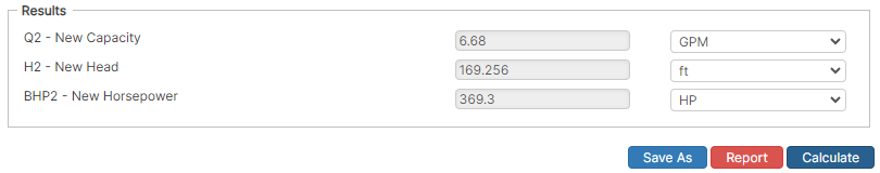
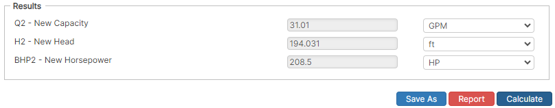
Results
- New Capacity (gpm)
- New Head (ft)
- New Horsepower (HP)
Diameter Change Only
Speed Change Only
Diameter and Speed Change Only
References
- ASME B31.4 – 1998 Edition “Pipeline Transportation Systems for Liquid Hydrocarbons and other Liquids”, Art. 404.1
- API 1117 – Movement of In-Service Pipelines
- API 5L, API 5LS and API 5LX – Specification of Pipe Grade
- ASTM – Various – Weld Joint Factor
- CFR Code Part 192
- MMS Regulations
- USDA-SCS Modified (Permissible Velocity of Water and Soil Erodibility)
- Pipeline Rules of Thumb Handbook