
Introduction
Hydrostatic testing is a method to determine strength, expose defects, expose leak & validate integrity of the vessel. Typically, tests are conducted at 125% of MAOP.
These tests are limited to defects that are ready for failure such as cracks. The test pressure must be adjusted for the related allowable stress at the design temperature. This requires adjustments during the testing phase due to ambient temperature conditions.
Volume of Water required to Fill Test Section
V=0.0408d^2L
V=0.0408d^2L
Where:
𝑉 − Volume of Water to Fill Test Section (gal)
𝑑 − Inside Pipe Diameter (in)
𝐿 − Length of the Test Section (ft)
Volume of Water required at Test Pressure
V_{tp}=VF_{wp}F_{pp}F_{pwt}
V_{tp}=VF_{wp}F_{pp}F_{pwt}Where:
𝑉𝑡𝑝 − Volume of Water at Test Pressure and Test Temperature (gal)
𝐹𝑤𝑝 − Correction Factor for the Compressibility of Water due to Inc of Pressure from 0 psi to Test Pressure
𝐹𝑝𝑝 − Correction Factor for Volume Change in Pipeline due to Increase of Pressure
𝐹𝑝𝑤𝑡 − Correction Factor for the Change of Pipe and Water Volume due to Temperature Change from Base to Test Temperature
F_{wp} = \frac{1}{1 – \left(4.5 \times 10^{-5}\right) \left(\frac{P}{14.73}\right)}
F_{wp} = \frac{1}{1 - \left(4.5 \times 10^{-5}\right) \left(\frac{P}{14.73}\right)}
𝑃 − Test Pressure (psi)
F_{pp} = 1 + \left[ \left(\frac{D}{\left(Wt\right)}\right) \left(\frac{0.91P}{30 \times 10^6} \right)\right] + \left[(3.68 \times 10^{-6} )(T_1 – 60)\right]
F_{pp} = 1 + \left[ \left(\frac{D}{\left(Wt\right)}\right) \left(\frac{0.91P}{30 \times 10^6} \right)\right] + \left[(3.68 \times 10^{-6} )(T_1 - 60)\right]
𝐷 − Pipe Outside Diameter (in)
𝑊𝑡 − Pipe Wall Thickness (in)
𝑃 − Test Pressure (psi)
𝑇1 − Test Temperature (°F)
F_{pt} = 1 + (18.2 \times 10^{-6})(T_1- 60 ) \~\ F_{pwt} = \frac{F_{pt}}{F_{wt}}
F_{pt} = 1 + (18.2 \times 10^{-6})(T_1- 60 ) \\~\\ F_{pwt} = \frac{F_{pt}}{F_{wt}}
𝐹𝑤𝑡 − Correction Factor for Thermal Change in Specific Water Volume from 60℉ to Test Water Temperature
\Delta P = \frac{(B – 2a)}{\frac{D(1 – \nu^2)}{Et} + C} \~\ B \times 10^6 = -64.268 + 17.0105T – 0.20369T^2 + 0.0016048^3
\Delta P = \frac{(B - 2a)}{\frac{D(1 - \nu^2)}{Et} + C} \\~\\ B \times 10^6 = -64.268 + 17.0105T - 0.20369T^2 + 0.0016048^3
Δ𝑃 − Pressure Change (psi/℃)
𝐵 − Coefficient of Expansion of Water
𝐷 − Pipe Outside Diameter (in)
𝐸 − Modulus of Elasticity for Steel 30×106 (psi)
𝑣 − Poisson′s Ratio
𝐶 − Compressibility Factor for Water
𝑎 − Coefficient of Expansion for Steel 1.116×10⁻⁵/℃
𝑡 − Pipe Wall Thickness (in)
𝑇 − Temperature (℃)
Case Guide
Part 1: Create Case
- Select the Pipeline Hydrostatic Testing application from the Testing Module
- To create a new case, click the “Add Case” button
- Enter Case Name, Location, Date and any necessary notes.
- Fill out all required Parameters.
- Make sure the values you are inputting are in the correct units.
- Click the CALCULATE button to overview results.
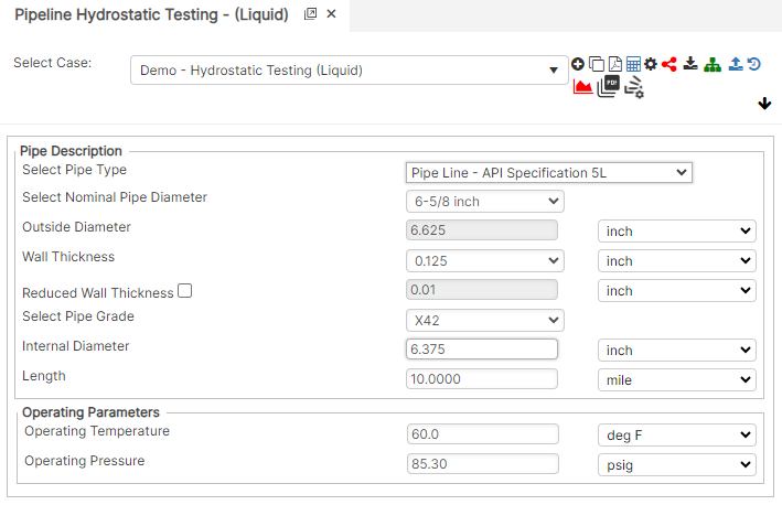
Input Parameters
- Nominal Pipe Size (in) : (0.625” – 48”)
- Outside Diameter (in)
- Wall Thickness (in) : (0.068”- >2”)
- Pipe Grade
- Internal Diameter (in)
- Pipeline Length (miles)
- Test Temperature (°F)
- Test Pressure (psig)
Part 2: Outputs/Reports
- If you need to modify an input parameter, click the CALCULATE button after the change.
- To SAVE, fill out all required case details then click the SAVE button.
- To rename an existing file, click the SAVE As button. Provide all case info then click SAVE.
- To generate a REPORT, click the REPORT button.
- The user may export the Case/Report by clicking the Export to Excel icon.
- To delete a case, click the DELETE icon near the top of the widget.
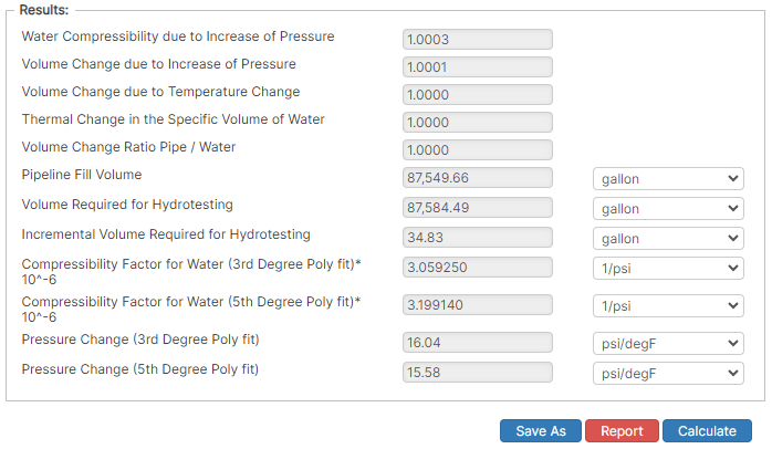
Results
- Water Compressibility due to Increase of Pressure
- Volume Change due to Increase of Pressure
- Volume Change due to Temperature Change
- Volume Change Ratio Pipe/Water
- Pipeline Fill Volume (gal)
- Volume Required for Hydrotesting (gal)
- Incremental Volume Required for Hydrotesting (gal)
- Compressibility Factor for Water (3rd Degree Poly fit) (in³/in³/psig) x10-6
- Compressibility Factor for Water (5th Degree Poly fit) (in³/in³/psig) x10-6
- Pressure Change (3rd Degree Poly fit) (psi/°F)
- Pressure Change (5th Degree Poly fit) (psi/°F).
References
- Pipeline Design for Hydrocarbons Gases and Liquids, Committee of pipeline planning, American Association of Civil Engineers, 1975
- Engineering Data Book, Volume II, Gas Processor Association, Revised Tenth Edition, 1994
- Pipeline Design & Construction, A Practical Approach, American Society of Mechanical Engineers, 2000
FAQ
-
Gas Purging Calculations?
Purging is a process of removing gas from the pipeline. Controlled purging of gases from pipelines by direct displacement with other gases that have been safely practiced for many years with the recognition that some flammable mixture is present. Purging of gases from pipelines by direct displacement with another gas also has been similarly practiced. It works both ways; however, there will always be an atmosphere of type of a mixture. This is due to the densities of the gases. Check Out
-
What are the differences between the Semiempirical Blowdown calculation and the AGA Blowdown calculation?
AGA blowdown calculation is based on the specification defined by American Gas Association. Semiempirical blowdown calculation was developed from the SW Research Report calculations for the blowdown time and mass of gas vented to atmosphere of a piping system. Check Out