Cathodic Protection Module Attenuation Calculation
Where long distances are covered by impressed current systems, voltage drops occur along the structure in a reduction fashion of voltages and currents.
Reductions can be significant depending on the current demand and voltage drops. This may require additional cathodic protection for the pipeline system.
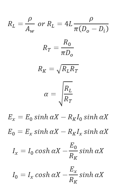
𝑅𝐿 — Linear Electrical Resistance of the Section of the Pipeline(ohm/m)
𝑅𝑇 — Leakage or Transverse Resistance of the Section of the Pipeline(ohm/m)
𝑅𝐾 — Characteristic Resistance of the Section of the Pipeline(Ohms)
𝛼 — Attenuation Constant of the Section of the Pipeline(Ohms)
𝑅0 — Pipe to Electrolyte Insulation Resistance(Ohms)
𝜌 — Specific Resistance of the Pipeline Material(Ohms)
𝐿 — Half Distance between Drain Points(anodes)(m)
𝐷𝑜 — External Diameter of the Pipeline(m)
𝐷𝑖 — Internal Diameter of the Pipeline(m)
𝐴𝑤 — Pipe Cross Sectional Area(,in-2.)
𝐸0 — Pipe to Electrolyte Potential at the Drain Point(Anode)(V)
𝐸𝑥 — Pipe to Electrolyte Potential at the Distance of X from the Drain Point(V)
𝐼0 — Current Flowing onto the Pipe at the Drain Point(Anode)(amp)
𝐼𝑥 — Current Flowing onto the Pipe at Distance X from the Drain Point(Anode)(amp)
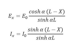
For typical pipeline with multiple drain points (anodes) with uniform spacing of 2L the potential and current are given:
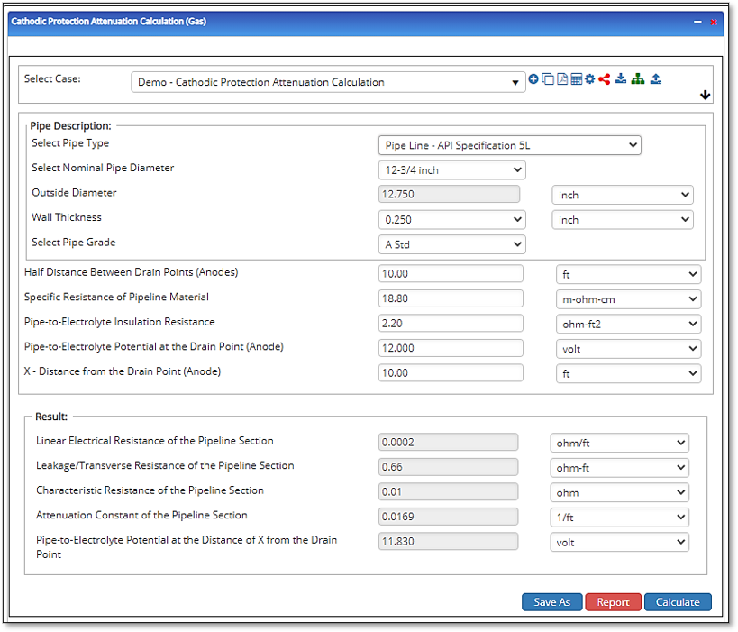
Input Parameters
- To create a new case, click the “Add Case” button
- Select the Cathodic Protection Attenuation Calculation application from the Cathodic Protection module list.
- Enter Case Name, Location, Date and any necessary notes.
- Fill out all required fields.
- Make sure the values you are inputting are in the correct units.
- Click the CALCULATE button.
- Pipe Outside Diameter
- Pipe Wall Thickness
- Half Distance between Drain Points (Anodes)
- Specific Resistance of Pipeline Material
- Pipe-to-Electrolyte Insulation Resistance
- Pipe-to-Electrolyte Potential at the Drain Point
- X – Distance from the Drain Point (Anode)
Outputs/Reports
- View the results.
- If an input parameter needs to be edited be sure to hit the CALCULATE button after the change.
- To SAVE, fill out all required case details then click the SAVE button.
- To rename an existing file, click the SAVE As button. Provide all case info then click SAVE.
- To generate a REPORT, click the REPORT button.
- The user may export the Case/Report by clicking the Export to Excel/PowerPoint icon.
- To delete a case, click the DELETE icon near the top of the widget.
- Linear Electrical Resistance of the Pipeline Section
- Leakage/Transverse Resistance of the Pipeline Section
- Characteristic Resistance of the Pipeline Section
- Attenuation Constant of the Pipeline Section
- Pipe-to-Electrolyte Potential at the Distance of X from the Drain Point