
Introduction
The Pipeline Toolbox is home to many tools and calculators. The PLTB User’s Guide presents information, guidelines, and procedures for use during design, construction, operations, and integrity tasks for field or office applications.
The Steel Pipeline Design & Stress Analysis module is intended to provide adequate analysis for public safety under all conditions encountered in the gas industry. Conditions that may cause additional stress in any part of a line or its appurtenances shall be provided for, using good engineering practice. Examples of such conditions include long self-supported spans, unstable ground, mechanical or sonic vibration, weight of special attachments, outside induced stresses, stresses caused by temperature differences, and the soil and temperature conditions.
Case Guide
Part 1: Create Case
- Select the Thrust at Blow-Off application from the Design & Stress Analysis Module
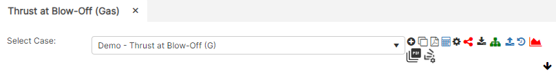
- To create a new case, click the “Add Case” button
- Enter Case Name, Location, Date and any necessary notes.
- Fill out all required Parameters.
- Make sure the values you are inputting are in the correct units.
- Click the CALCULATE button to overview results.
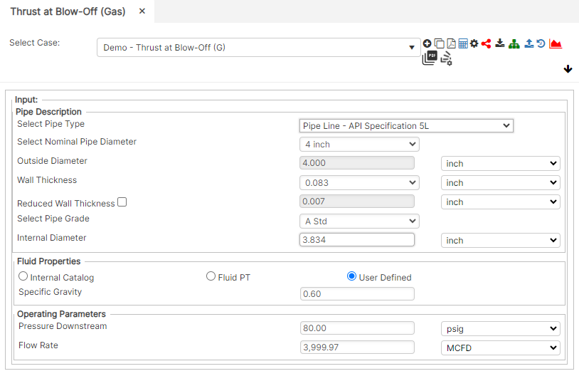
Input Parameters
- Nominal Pipe Size (in): (0.625” – 48”)
- Outside Diameter (in)
- Wall Thickness (in): (0.068”- >2”)
- Pipe grade: (24000psi-80000psi) (if unknown use Grade A 24000)
- Internal Diameter (in)
- Specific Gravity
- Pressure Downstream (psig)
- Flow Rate (MCFD)
Part 2: Outputs/Reports
- If you need to modify an input parameter, click the CALCULATE button after the change.
- To SAVE, fill out all required case details then click the SAVE button.
- To rename an existing file, click the SAVE As button. Provide all case info then click SAVE.
- To generate a REPORT, click the REPORT button.
- The user may export the Case/Report by clicking the Export to Excel icon.
- To delete a case, click the DELETE icon near the top of the widget.
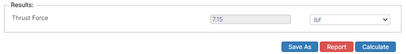
Results
- Thrust Force (lbf)
References
- ASME B31.8 – Gas Transmission and Distribution Piping Systems
- API 5L, API 5LS and API 5LX – Specification of Pipe Grade
- ASTM – Various – Weld Joint Factor
- CFR Code Part 192
- USDA-SCS Modified (Permissible Velocity of Water and Soil Erodibility)
- FHWA-HEC
- Pipeline Rules of Thumb Handbook
- Timoshenko, S – Theory of Elasticity Anchor Force
FAQ
-
Restrained versus Unrestrained Pipe (Difference in Gas vs. Liquid)?
ASME B31.4 liquid and B31.8 gas codes include calculations for the net longitudinal compressive stress that must be applied only for a restrained line that equates to a low (less than 2%) longitudinal strain. This stress status is characteristic to underground pipelines located some distance away from above ground piping facilities.
Unrestrained lines means those above ground sections of piping without axial restraint as with buried pipe with soil. In others words the soil exerts substantial axial restraint, but not fully restrained. Check Out
-
What is the Maximum Span Length of rev1?
Regarding span factors with and without water are based on bending stress and deflection. Larger diameter pipe spans require saddles for stability. Many standards that require pipes to be filled with water are based on bending and shear stresses not to exceed 1,500 psi and a deflection between supports not exceed 0.1 inches. Check Out
-
What is the model used for Thrust at Blow-Off?