
Introduction
Design pressure for steel pipe is calculated using Barlow’s Equation. The design pressure for steel pipe is determined in accordance with the following formula: P=\frac{2ST}{D}FET
P=\frac{2ST}{D}FETWhere:
P = Design pressure in pounds per square inch (kPa) gage
S = Yield strength in pounds per square inch (kPa) determined in accordance with 192.107
D = Nominal outside diameter of the pipe in inches (millimeters)
t = Nominal wall thickness of the pipe in inches (millimeters). If this is unknown, it is determined in accordance with 192.109. Additional wall thickness required for concurrent external loads in accordance with 192.103 may not be included in computing design pressure.
F = Design factor determined in accordance with 192.111
E = Longitudinal joint factor determined in accordance with 192.113
T = Temperature derating factor determined in accordance with 192.115
Design Factor (F) for Steel Pipe
A design factor of 0.72, except that a design factor of 0.60 is used for pipe, including risers, on a platform located offshore or on a platform in inland navigable waters, and 0.54 is used for pipe that has been subjected to cold expansion to meet the specified minimum yield strength and is subsequently heated, other than by welding or stress relieving as a part of welding, to a temperature higher than 900°F (482°C) for any period of time or over 600°F (316°C) for more than 1 hour.
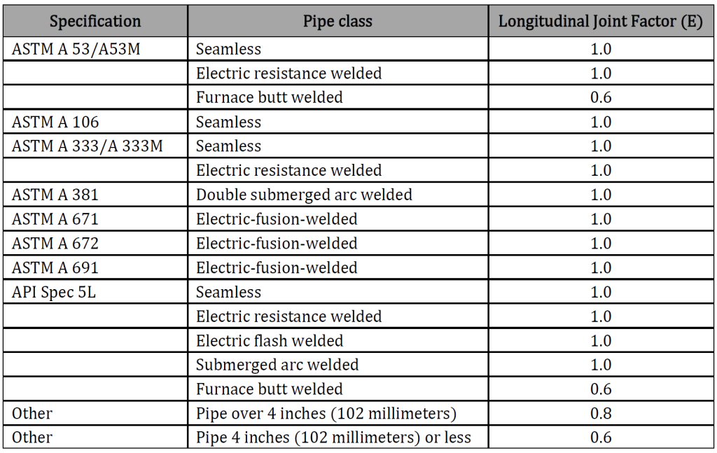
Longitudinal Joint Factor (E) for Steel Pipe Table
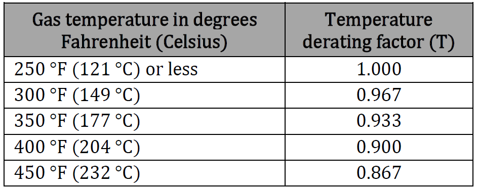
Temperature Derating Factor (T) for Steel Pipe Table
Case Guide
Part 1: Create Case
- Select the Design Pressure – Steel Pipe ASME B31.4 application from the Design & Stress Analysis Module
- To create a new case, click the “Add Case” button
- Enter Case Name, Location, Date and any necessary notes.
- Fill out all required Parameters.
- Make sure the values you are inputting are in the correct units.
- Click the CALCULATE button to overview results.
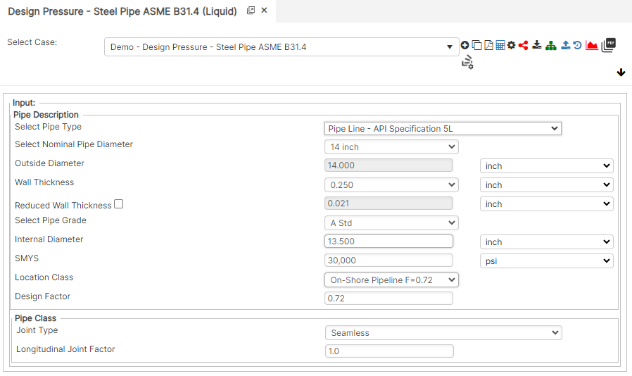
Input Parameters
- Nominal Pipe Size (in): (0.625” – 48”)
- Wall Thickness (in): (0.068”- >2”)
- Pipe grade: (24000psi-80000psi) (if unknown use Grade A 24000)
- Outside Pipe Diameter (in)
- Internal Pipe Diameter (in)
- SMYS (psi)
- Location Class
- Design Factor: Reference 49 CFR 192.611
- Joint Type (Dropdown)
- E – Longitudinal Joint Factor
Part 2: Outputs/Reports
- If you need to modify an input parameter, click the CALCULATE button after the change.
- To SAVE, fill out all required case details then click the SAVE button.
- To rename an existing file, click the SAVE As button. Provide all case info then click SAVE.
- To generate a REPORT, click the REPORT button.
- The user may export the Case/Report by clicking the Export to Excel icon.
- To delete a case, click the DELETE icon near the top of the widget.
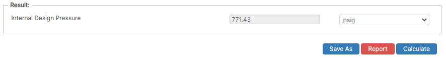
Results
- Internal Design Pressure (psig)
References
- ASME B31.8 – Gas Transmission and Distribution Piping Systems
- API 5L, API 5LS and API 5LX – Specification of Pipe Grade
- ASTM – Various – Weld Joint Factor
- CFR Code Part 192
- MMS Regulations
- USDA-SCS Modified (Permissible Velocity of Water and Soil Erodibility)
- FHWA-HEC
- Pipeline Rules of Thumb Handbook
FAQ
-
Restrained versus Unrestrained Pipe (Difference in Gas vs. Liquid)?
ASME B31.4 liquid and B31.8 gas codes include calculations for the net longitudinal compressive stress that must be applied only for a restrained line that equates to a low (less than 2%) longitudinal strain. This stress status is characteristic to underground pipelines located some distance away from above ground piping facilities.
Unrestrained lines means those above ground sections of piping without axial restraint as with buried pipe with soil. In others words the soil exerts substantial axial restraint, but not fully restrained. Check Out
-
What is the Maximum Span Length of rev1?
Regarding span factors with and without water are based on bending stress and deflection. Larger diameter pipe spans require saddles for stability. Many standards that require pipes to be filled with water are based on bending and shear stresses not to exceed 1,500 psi and a deflection between supports not exceed 0.1 inches. Check Out
-
What is the model used for Thrust at Blow-Off?