Restrained pipes are typically buried with proper bedding. However, when settlement or subsidence occurs the longitudinal and combined stresses may be replaced with a strain limit of 2% in ASME B31.4
Yielding that does not impair the serviceability of the pipe. Local stresses caused by periodic or repetitive load resulting in fatigue. Unanticipated earthquakes vibration and thermal expansion.
𝑆𝐻 − Hoop stress(psi)
𝑃 − Pipe internal pressure(psi)
𝐷 − Pipe outside diameter(in)
𝑡 − Pipe wall thickness(in)
Hoop Stress

𝑃 − Pipe internal pressure(psi)
𝐷 − Pipe outside diameter(in)
𝑡 − Pipe wall thickness(in)
Longitudinal Stress due to Internal Pressure
𝑆𝑃 = 0.3𝑆𝐻
𝑆𝑃 − Longitudinal stress due to internal pressure(psi)
𝑆𝐻 − Hoop stress(psi)
Longitudinal Stress due to Thermal Expansion
𝑆𝑇 = 𝐸𝛼(𝑇1−𝑇2)
𝑆𝑇 − Longitudinal stress due to thermal expansion(psi)
𝛼 − Coefficient of thermal expansion(1/℉)
𝐸 − Elastic modulus of ambient temperature(psi)
𝑇1 − Pipe Temperature at the time of instalation(℉)
𝑇2 − The warmest or coldest pipe operating temperature(℉)
Nominal Bending Stress

𝑆𝐵 − Nominal bending stress(lb/in)
𝑀 − Calculated bending moment
𝑍 − Pipe section modulus(in3)
Stress due to Axial Loading

𝑆𝑋 −Axial loading stress(lb/in)
𝑅 −External for axial component(lb)
𝐴 −Pipe metal cross sectional area(in2)
Net Longitudinal Stresses
𝑆𝐿 − Net longitudinal stress in restrained pipe(psi)
Note: The maximum permitted value for is 0.9ST
𝑆 − Specified minimum yield strength(psi)
𝑇 − Temperature derating factor
Combined Biaxial Stress
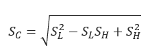
𝑆𝐶 −Combined biaxial stress(psi)
Note: The maximum permitted value of 𝑆𝐶. is 𝑘𝑆𝑇
𝑘 ≤ 0.9−for load of long duration
𝐾 = 1.0−for occasional nonperiodic loads of short duration
𝑆 − Specified minimum yield strength(psi)
𝑇 − Temperature derating factor
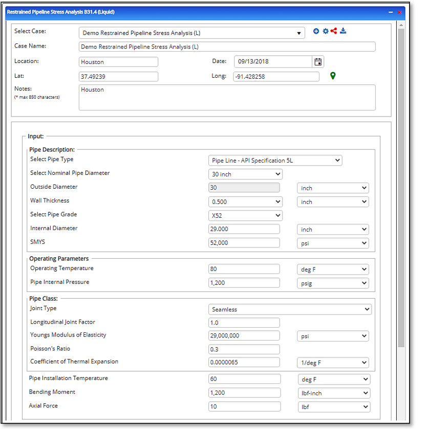
Input Parameters
- Select the Restrained Pipeline Stress Analysis application from the Steel Pipe – Design and Stress Analysis module.
- To create a new case, click the “+” button
- Enter Case Name, Location, Date and any necessary notes.
- Fill out all required fields.
- Make sure the values you are inputting are in the correct units.
- Click the CALCULATE button.
- Nominal Pipe Size(in)
- Wall Thickness(in)
- Pipe grade (if unknown, use Grade A 24000)
- T – Temperature Derating Factor
- Pipe Internal Pressure
- Pipe Installation Temp
- Pipe Operating Temp
- Nominal Bending Stress(psi)
- Stress due to Axial Load(psi)
- k – Load Factor while providing Poisson’s Ratio
- Young’s Modulus of Elasticity
- Thermal Expansion Coefficient(1/°F)
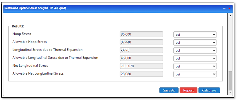
Outputs/Reports
- View the results.
- If an input parameter needs to be edited be sure to hit the CALCULATE button after the change.
- To SAVE, fill out all required case details then click the SAVE button.
- To rename an existing file, click the SAVE As button. Provide all case info then click SAVE.
- To generate a REPORT, click the REPORT button.
- The user may export the Case/Report by clicking the Export to Excel/PowerPoint icon.
- To delete a case, click the DELETE icon near the top of the widget.
- Hoop Stress(psi)
- Longitudinal Stress due to Internal Pressure(psi)
- Longitudinal Stress due to Thermal Expansion(psi)
- Net Longitudinal Stress(psi)
- Maximum Permitted Longitudinal Stress(psi)
- Combined Biaxial Stress(psi)
- Maximum Permitted Combined Biaxial Stress(psi).