
The ASME Code requires that capacity certification be obtained for PRVs designed for liquid service. The procedure for obtaining capacity certification includes testing to determine the rated coefficient of discharge for the liquid PRVs at 10 % overpressure.
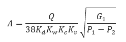
The sizing equations for pressure-relief devices in liquid service provided in this section assume that the liquid is incompressible (i.e. the density of the liquid does not change as the pressure decreases from the relieving pressure to the total backpressure).
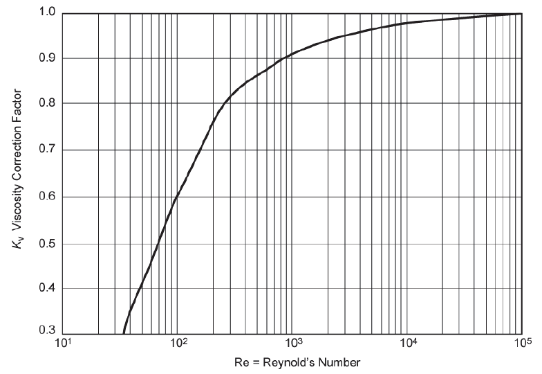
When a PRV is sized for viscous liquid service, it should first be sized as if it were for a non viscous type application (i.e. Kv = 1.0) so that a preliminary required discharge area, A, can be obtained from the equations above. From API 526 standard orifice sizes, the next orifice size larger than A should be used in determining the Reynold’s Number, Re, from either of the following relationships.
Non-Viscous Application
Viscous Application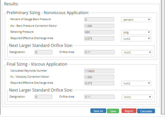
Where:
𝐴 − the required effective discharge area (in2)
𝑄 − the flow rate (gal/min)
𝐾𝑑 − the rated coefficient of discharge
𝐾𝑤 − correction factor due to backpressure
‒ if the backpressure is atmospheric, use a value for Kw of 1.0. Balanced bellows valves in backpressure service will require the correction factor determined from Figure 31. Conventional and pilot-operated valves require no special correction
𝐾𝑐 − combination correction factor for installations with a rupture disk upstream of the PRV
‒ 1.0, when a rupture disk is not installed;
‒ 0.9, when a rupture disk is installed in combination with a PRV and the combination does not have a certified value;
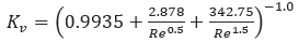
𝐾𝑣 − correction factor due to viscosity
Where:
𝐺1 − the specific gravity of the liquid at the flowing temperature referred to water at standard conditions
𝑃1 − upstream relieving pressure (psig)
𝑃2 − total backpressure (psig)
When a PRV is sized for viscous liquid service, it should first be sized as if it were for a non viscous type application (i.e. Kv = 1.0) so that a preliminary required discharge area, A, can be obtained from the equations above. From API 526 standard orifice sizes, the next orifice size larger than A should be used in determining the Reynold’s Number, Re, from either of the following relationships.
Where:
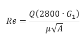
𝑅𝑒 − Reynolds Number
𝑄 − flow rate at the flowing temperature (gal/min)
𝐺1 − the specific gravity of the liquid at the flowing temperature referred to water at standard conditions
𝐴 − the required effective discharge area (in2)
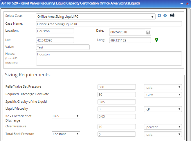
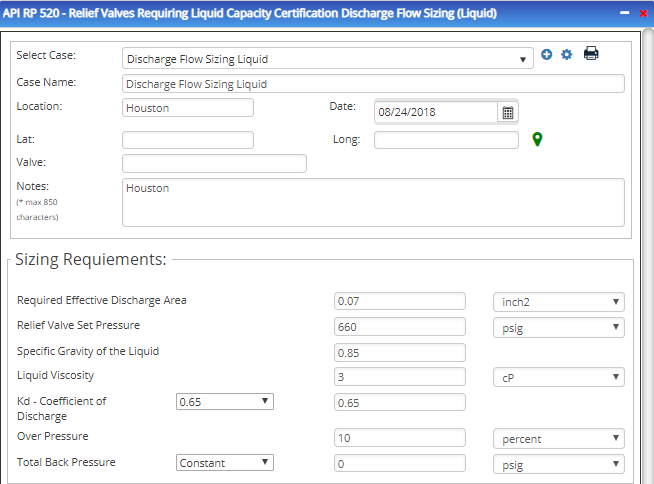
Input Parameters
- To create a new case, click the “Add Case” button
- Select the API 520 – Relief Valves Requiring Capacity Certification application from the Pipeline Facilities section.
- Select either the Flowrate or Effective Discharge Area calculation.
- Enter Case Name, Location, Date and any necessary notes.
- Fill out all required fields.
- Make sure the values you are inputting are in the correct units.
- Click the CALCULATE button.
- Required Effective Discharge
- Relief Valve Set Pressure (psig)
- Specific Gravity of Liquid
- Liquid Viscosity
- Kd- Coefficent of Discharge
- Overpressure %
- Total Back Pressure (psig)
Outputs/Reports
- View the results.
- If an input parameter needs to be edited be sure to hit the CALCULATE button after the change.
- To SAVE, fill out all required case details then click the SAVE button.
- To rename an existing file, click the SAVE As button. Provide all case info then click SAVE.
- To generate a REPORT, click the REPORT button.
- The user may export the Case/Report by clicking the Export to Excel/PowerPoint icon.
- To delete a case, click the DELETE icon near the top of the widget.
Non-Viscous Application
- Percent of Gauge Back Pressure (%)
- Kw – Back pressure Correction Factor
- Relieving Pressure (psig)
- Required Discharge Flow Rate (gal/min)
- Next larger Standard Orifice Size
Viscous Application
- Calculated Reynolds Number
- Kv – Viscosity Correction Factor
- Required Discharge Flow Rate (gal/min)
- Next Larger Standard Orifice Size