
Why do Pipelines Fail?
Leaks and ruptures are the primary modes of failure which result from flaw growth such as corrosion and stresses such as mechanical damage from 3rd part hits on a pipeline. This procedure will be primarily focusing on time-dependent defects such as external and internal corrosion. However, it must be understood the interaction of other defects with corrosion cannot be ignored and must be considered when assessing the integrity of the pipe. Below are examples of flaw growth versus stresses.Flaw Growth Stresses (Ductile, Brittle, Toughness Loading)
External Corrosion Mechanical Damage
Internal Corrosion Pressure Increase and or changes
SCC Pipe Movement
Erosion Thermal
Note: The goal of this RSTRENG procedure is to manage pipeline facility assets effectively and to reduce risk to meet the industry’s goal of zero leaks.
Flawless Pipe
- What is known about pipeline grade steel pipe when new joints arrive on-site:
- Nominal OD and wall thickness
- Specified minimum yield strength (SMYS)
- How the joints were manufactured
- Joint lengths and end specifications
- Each joint has been pressure tested for a few seconds.
- Coating type and nominal thicknesses, if any
- What is not known:
- Actual pressure that will cause the pipe wall to yield
- Additional pressure beyond yield that will cause failure
- What may not have been recorded or known after a joint has been welded, lowered in the ditch, backfilled, and placed into operation:
- Bending that occurred during construction
- Dents and gouges that may have occurred at any time, but have not caused a failure.
- Stress in the pipe wall from these possible sources and potential added stresses from pressure tests and fluctuating high operating or surge pressures.
- Areas of the pipe wall that have lost metal from corrosion
Locate and Define Coating Holidays and Pipe Defects
To assess the integrity of the line pipe in each covered segment is accomplished by applying one or more of the following methods depending on the threat(s) to which the covered segment is susceptible to risk exposure. It may be necessary to run one or all of the methods depending on the risks and pre-assessment analysis.In-Line Inspection (ILI)
ILI tool(s) are capable of detecting corrosion as well as other threats to which the covered segment is susceptible in accordance with ASME/ANSI B31.8S, Section 6.2.Pressure Test (Hydro)
Pressures tests are specified in Table 3 of section 5 of ASME /ANSI B31.8S, to justify an extended reassessment interval in accordance with §192.939.Direct Assessment (DA)
Direct Assessment is used to address threats of external corrosion, internal corrosion, and stress corrosion cracking in accordance with the requirements listed in §192.923 and with, as applicable, the requirements specified in §192.925, §192.927, or §192.929.Other Technology
The use of technologies that have demonstrated an equivalent understanding of the condition of the line pipe. Guided Wave Testing (GWT) is one such technology that can be found in NACE SP Guided Wave Testing for Piping Applications.Excavations/Direct Examinations
Direct examination steps are used to calibrate and validate the prioritization of survey indications and their severity. In addition, field verification of reported ILI, GWT, DA features must be done to help confirm:- Reported Critical Features [Incomplete on User Manual]
- Tool Performance [Incomplete on User Manual?]
- Traceable
- Verifiable
- Complete
Direct Examination Step
Verification of ILI runs, DA surveys or prioritization of excavations is the biggest challenge for the operator. The following is a process for this step:- Prioritization
- Scheduling the excavations
- Excavating
- Assessment of coating damage and corrosion defects
- NACE SP0502
- ASME B318.S
- Evaluation of remaining strength of the pipe segment
- B31.G
- Modified B31.G
- RSTRENG
- Root cause analysis
- Re-prioritization of priorities and reclassifying indications
- Mitigation (4 Rs)
- Repair
- Replace
- Reduce Pressure
- Recoat
Excavations
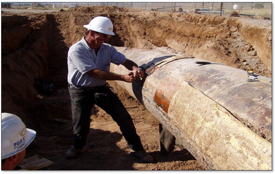
Excavations – Coating Removal
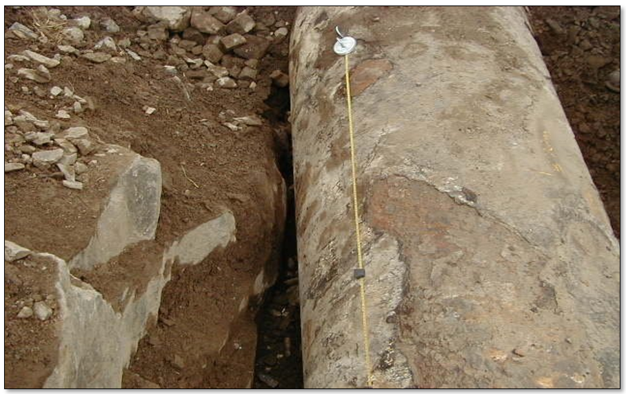
Excavations – Rock & Coating
Site Analysis and Documentation
Industry standards, regulatory requirements, and operator protocols must be followed to achieve consistency with data collection. Some of these standards include and not limited are as follows:- ASME B31.8, B31.3, etc.
- API 579, 1169, 1163, etc.
- NACE ILI, GWT, ECDA, ICDA, etc.
- ASNT ILI PQ-2003, In-Line Inspection Personnel Qualification and Certification
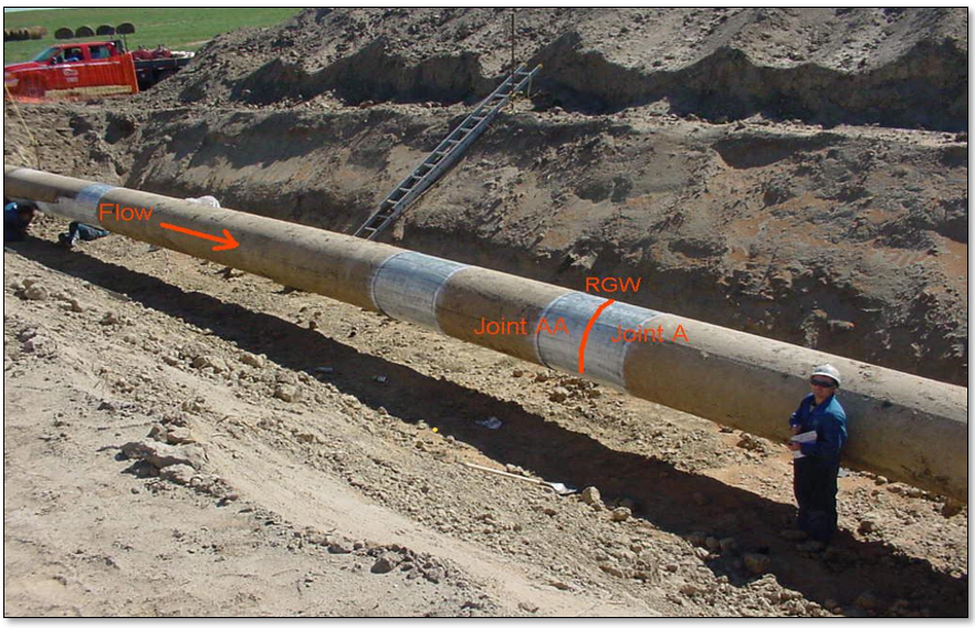
- Feature location identification
- ILI odometer readings from nearest weld
- Chainage from DA Surveys
- GPS
- Use other sources of information such as:
- As-Built drawings
- Survey plots
- One calls data
- Excavation starts/ends with reference girth weld identification
- Description of terrain and other features
- Description of coating type and condition
- Characterization of corrosion and deposits
- Pipe condition
- 2D Photos of pipe surface defects
- 3D Scans of individual defects and interaction
- Pipe surface preparation type and condition
- Assessments and measurement data
- Traceable records are those which can be clearly linked to original information about a pipeline segment or facility.
- Verifiable records are those in which information is confirmed by other complementary, but separate, documentation.
- Complete records are those in which the record is finalized as evidenced by a signature, date, or other appropriate markings.
Corrosion Mapping Tools
There are many types of tools that are used in the pipeline industry to assess time-dependent defects such as external or internal corrosion.Non-Destructive Testing (NDT)
- NDT is an analysis technique used to determine the state or function of a system by comparing a known input with a measured output, without the use of invasive approaches like disassembly or failure testing.
- NDT also called ultrasonic testing (UT), an ultrasound transducer connected to a diagnostic machine is passed over the object being inspected. The transducer is typically separated from the test object by acouplant (such as oil) or by water, as in immersion testing.
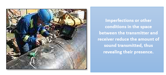 There are two methods of receiving the ultrasound waveform, reflection, and attenuation. In reflection (or pulse-echo) mode, the transducer performs both the sending and the receiving of the pulsed waves as the “sound” is reflected back to the device. Reflected ultrasound comes from an interface, such as the back wall of the object or from an imperfection within the object. The diagnostic machine displays these results in the form of a signal with an amplitude representing the intensity of the reflection and the distance, representing the arrival time of the reflection. In attenuation (or through-transmission) mode, a transmitter sends ultrasound through one surface, and a separate receiver detects the amount that has reached it on another surface after traveling through the medium.RSTRENG ECDA_NDT Image.png
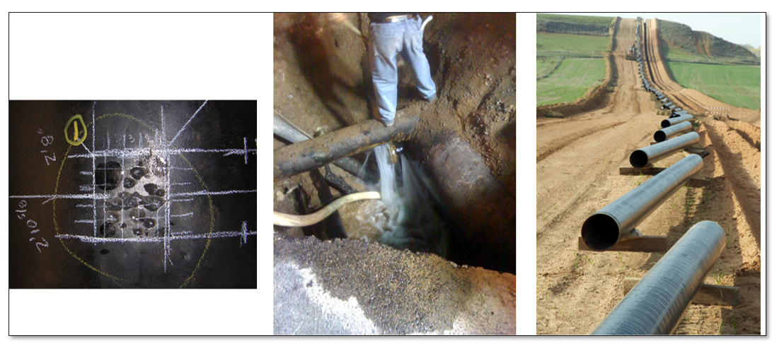
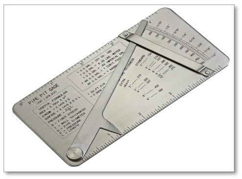
Pit Gauges (Manual)
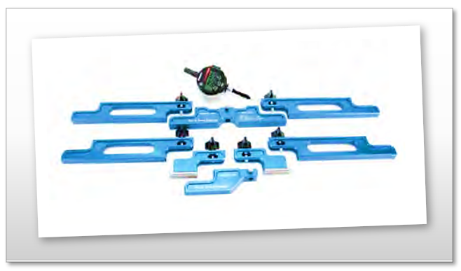 Pit gauges are used to determine corrosion allowances for equipment wherever metal loss affects materials, such as pipelines, vessels, piping, storage tanks, oil country tubular goods, drill pipe, bottom hole assemblies, bridges and other structures. Various types are available for different applications, including the Flat Gage for basic evaluation and the Bridging Pit Gauge for evaluating large areas of weight loss corrosion.
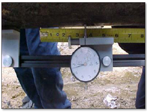 Bridging Pit Gauge allows the Corrosion Inspector to Span over or Cantilever into Large Areas of Weight-Loss Corrosion, to obtain accurate and consistent measurements, or cross-sections, of Pit Depth.
 Bridging with Dial Indicator [Slide 170]
Flat Pit Gage is the most universal tool to measure localized external pitting on pipe and vessel surfaces. These gages should be used only for screening corrosion.
Bridging with Dial Indicator [Slide 170]
Flat Pit Gage is the most universal tool to measure localized external pitting on pipe and vessel surfaces. These gages should be used only for screening corrosion.
Pit Gage Measurements
- Pitting and Corrosion (TRACEABLE)
- Inspection problem – Pitting on a regulated pipeline must be assessed by a trained, certified and operator qualified person. If the pitting is assessed to be severe, the pipe may need to be repaired or replaced as a cylinder. Identifying these areas of concern to the operator’s records where they do not meet industry standards requires training not only in field pitting measurements but also in understanding ASME B31.G, Modified B31.G, and RSTRENG assessments.
- Requirements (VERIFIABLE)
- Measurements – The depth(s) of pitting must be measured and verified by a qualified person who has training and certification for this task on a regulated pipeline operation. If these field measurements cannot be verified, then the operator has no way to measure their performance at the beginning of their integrity program and periodically evaluate the results of these measures to monitor and evaluate the effectiveness of the program.
- New technologies such as 3D Structured Light can improve an operator’s ability to prevent certain types of failures, detect threats more effectively or improve the mitigation of these threats. Pipeline operators should avail themselves of these technologies as they become proven and practical in the field.
- Assessments (COMPLETE)
- RSTRENG, B31G, and Modified B31.G are industry-approved programs designed to calculate the safe operating pressures of corroded pipe for complete documentation. Training with certification is required to understand when and how to use these programs. The operator must understand these limitations, interaction of pitting, other defects, materials, as well as stresses that could negate the results of these programs.
3D Structured Light Toolbox
- The 3D Toolbox is a portable, field-ruggedized system for measuring and analyzing metal loss and mechanical damage on tanks, vessels, and pipes. The process is a simple, four (4) step approach to meet the stringent regulatory requirements of TVC (Traceable, Verifiable, and Complete):
- Validate calibration
- Measure the 3D pipe features/defects using the 3D Camera
- Analyze the 3D features to identify features of interest
- Export data features for post-processing and reporting
- ASME B31.G, ASME B31.G Modified, and RSRTENG for corrosion
- ASME B31.8 and ASME B31.8 Modified for dents analysis
- System Components
- 3D Camera
- Power Supplies and Adopters
- Cables
- Panasonic Toughbook
- Monopod
- Accessories (Batteries, Backpacks, Tripods, Tractors, etc.)
- 3D Structured Light
- Measures surface defects (Length, Width, and Depth – X, Y & Z)
- Uses the Pipeline (PL) Analysis Tool for most common subsurface or above surface defects including welds
- Calculates remaining strength of corroded pipe (Level 1 and 2)
- Calculates the % Depth and Stress-Strain (Level 1 and 2)
- Produces Corrosion and Dent reports to meet regulatory requirements for TV
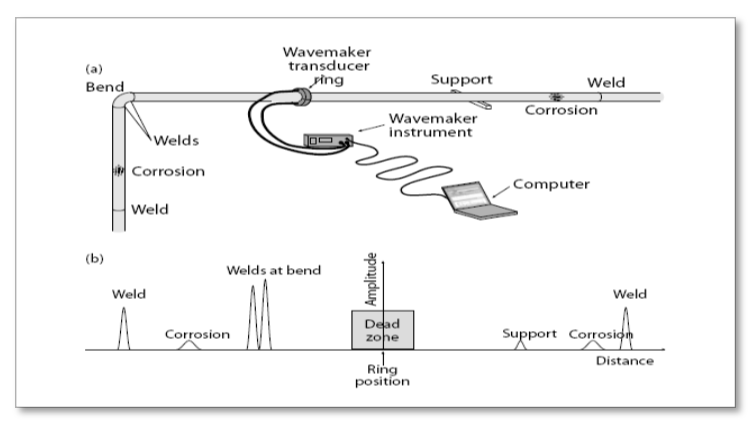
Guided Wave Testing (GWT)
- GWT is an NDT technique for assessing long runs of pipe for metal wall loss caused by either internal/external corrosion or erosion and cracking. This technique can be used on pipes in soil, underneath insulation, cased crossings, offshore risers, through wall areas, heat exchanger tubes, etc. A set of arrays that consist of transducer elements are used which behave like a conventional ultrasonic transducer operating in pulse-echo mode. The ring sends out a burst of ultrasonic guided waves and then listens to signals that are reflected back as with conventional NDT.
Magnetic Particle Inspection (MPI)
 A nondestructive inspection technique for locating surface cracks in steel using fine magnetic particles and a magnetic field. See also ASTM E 709.10
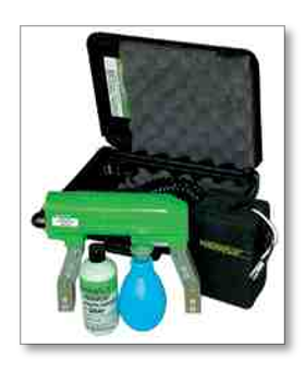
Dye Penetrant Inspection (DPI)
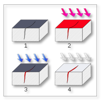 DPI is also called liquid penetrant inspection (LPI), is a widely applied and low-cost inspection method used to locate surface-breaking defects in all non-porous materials (metals, plastics, or ceramics). The penetrant may be applied to all non-ferrous materials, but for inspection of ferrous components, magnetic-particle inspection is preferred for its subsurface detection capability. LPI is used to detect casting and forging defects, cracks, and leaks in new products, and fatigue cracks on in-service components.
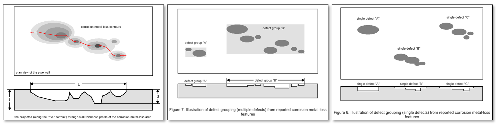
Identify & Classify Indications
The first step is to locate, identify and classify indications from ILI, DA, GWT, etc. surveys as listed below in Table 1 Coating Holidays and Pipe Defects. The primary focus for the procedure is corrosion; however, the user must be aware of cracks, mechanical damage, and other threats that may impact the safe pressure calculations. Table 1 Coating Holidays and Pipe Defects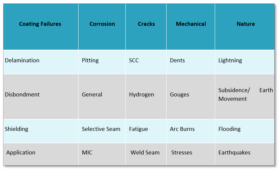
Report Critical Features from ILI
Results of the in-line inspection primarily provide features (indications) of wall loss defects with some characterization (classification) of the defect. Screening of this information is required in order to determine the time frame for examination and evaluation. Direct Examination consists of a variety of direct inspection techniques including visual inspection, inspections using NDE equipment, and taking 3D Structured Light measurements in order to characterize the defect in verification bell holes where anomalies are detected. Once the defect is identified and classified, an evaluation of the defect must be made in order to determine the appropriate mitigation actions.ILI Tool Performance
The effectiveness of an in-line inspection depends on the accuracies of the inspection system and the philosophy used by the pipeline company in investigating reported defects. Most in-line inspection companies report minimum detection thresholds of 5 to 10 percent of the wall thickness; below this depth, defects are not reported. Above the detection threshold, detection reliability is assumed to be high, near, or above 95 percent. Sizing accuracies are typically given as ±10 percent of the wall thickness with 80 percent confidence (i.e., four out of five defects are sized to within 10 percent of their actual depths). Somewhat lower sizing accuracies are often given for pit-like defects that are short or narrow. Investigation and repair strategies vary with each pipeline company. In most cases, a company will investigate (dig and examine) reported defects until the calculated failure pressure of the remaining defects is above an acceptable level, which is usually set as a percentage of the yield pressure or maximum allowable operating pressure (MAOP). For example, an operator may excavate and investigate reported defects until the calculated failure pressure of all remaining defects is at least 1.25 times the MAOP based on the reported defect geometries. See also:- Determining Yield Pressure
- Setting Operating Pressure
Prioritization of Indications
The strategy used by the pipeline company to investigate areas adjacent to reported defects also impacts the effectiveness of the in-line inspection. If the pipeline company automatically extends bell holes until there is no indication of damaged coating and/or no indications of corrosion, the effectiveness is increased. The effectiveness increases because the pipeline company discovers coating faults and metal-loss defects that may not have been located by the inspection run. Consequently, the overall effectiveness of an in-line inspection depends on many factors, including the smart-pig accuracy, the pipeline company’s philosophy of investigating reported defects, and the pipeline company’s strategy for extending bell holes.ILI Effectiveness
Representative effectiveness of an in-line inspection for comparison with other methods of assessing pipeline integrity can be calculated in a manner similar to that for a pressure test.Remaining life = Growth fraction * wall thickness/growth rate
Where the growth fraction is determined for the reported defect with the smallest predicted failure pressure. Alternatively, statistical (probabilistic) analyses are possible using the reported defect distribution.Data Requirements and Report Results
Below are the data requirements that must be documented in order to meet the TVC requirements for a direct examination:- General Information
- Project
- Line name or ID
- Site Location
- Date
- Inspector’s name
- Contractor name
- ILI information
- Description of Anomaly/Feature
- Wheel Count (WC)
- Anomaly/Feature type
- O’clock position
- Length, width, depth
- Upstream (U/S) reference i.e. weld description and WC
- Location Information
- Alignment sheet number
- Upstream engineering station number and U/S weld reference
- Anomaly distance from U/S reference
- Pipe Information
- Outside Diameter (OD)
- Nominal wall thickness (WT)
- Measured WT adjacent to an anomaly
- Seam type
- Coating information
- Coating type
- Coating condition
- Holiday size
- Shielding – high dielectric materials
- Girth Welds and Pipe Seams
- Girth weld reference number
- Long seam o’clock position
- Joint length
- Mechanical Damage – Dents
- Type (Characterization)
- Distance from U/S girth weld
- Length, width, depth, o’clock position
- Remaining WT
- Verification (3D Tools, NDE, etc.)
- Metal Loss – Corrosion
- Type (Characterization)
- Distance from U/S girth weld
- Length, width, depth, o’clock position
- Remaining WT
- Verification (3D Tools, NDE, etc.)
- Planar Flaws – Cracks
- Type (Characterization)
- Distance from U/S girth weld
- Length, width, depth, o’clock position
- Remaining WT
- Verification (3D Tools, NDE, etc.)
- Repair Information
- Reduce Pressure
- Repair
- Type B pressurized sleeve
- Type A reinforcing sleeve
- Composite reinforcing sleeve
- Direct weld metal deposition
- Leak clamp
- Grind or buff out
- Replace Cylinder of Pipe
- Recoat
- Dig Site Sketch
- Locations of reference welds and other features
- ILI sheets
- Photos
- 360 Degree topography
- Before excavation
- Excavation site
- Clean up
- Exposed pipe
- Anomalies
- Before cleaning
- After cleaning
- Identification marks with flow direction
- Completed repair(s) and mitigation
- 360 Degree topography
- Documentation (Complete)
- Written summary of all assessments, work performed and results
Mitigation and Repair
Defects discovered during initial inspections shall be addressed by a pipeline operator repair plan. These plans include the methods and timing of all repairs. Operators are required to make repairs in accordance with a prioritized repair schedule established by considering the results of a risk assessment and the severity of conditions discovered in the pipeline. The required repair schedule interval begins at the time the condition is discovered such as an ILI run. Defect repairs can be divided into three groups and repair intervals. Performance-based repairs are determined by engineering critical assessments (ECAs).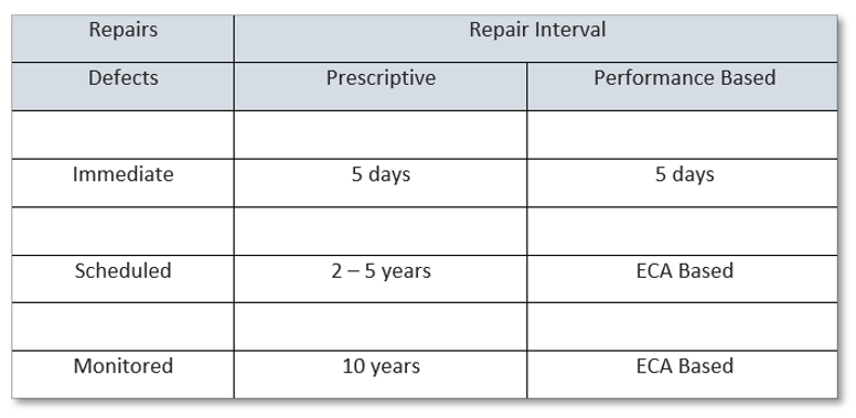 All repairs are made with materials and processes that are suitable for the pipeline operating conditions. Defect Repairs include the following practices:
- Reduce Pressure
- Repair
- Type B pressurized sleeve
- Type A reinforcing sleeve
- Composite reinforcing sleeve
- Direct weld metal deposition
- Leak clamp
- Grind or buff out
- Replace Cylinder of Pipe