
Types of Corrosion Measurements
Factors for selecting a Level for analysis of a corroded area include quantity and quality of data available with which to perform an evaluation. The least understood issue in making corrosion assessments include:
- Type of tools to accurately measure corrosion pitting
- Common Field Type Gauges
- Flat pit gauge
- Spanning or bridging pit gauge
- 3D Technologies
- Structured Light
- Laser
- Pipe preparation
- Remove Coating
- Abrasive blast clean pipe to remove all scale and deposit
- Establish Grids and Points of Reference
- Visually Inspect for Other Defects
- Training and certification of individuals making these assessments
- NACE
- ASNT
- OQ
- Documentation
- Common Field Type Gauges
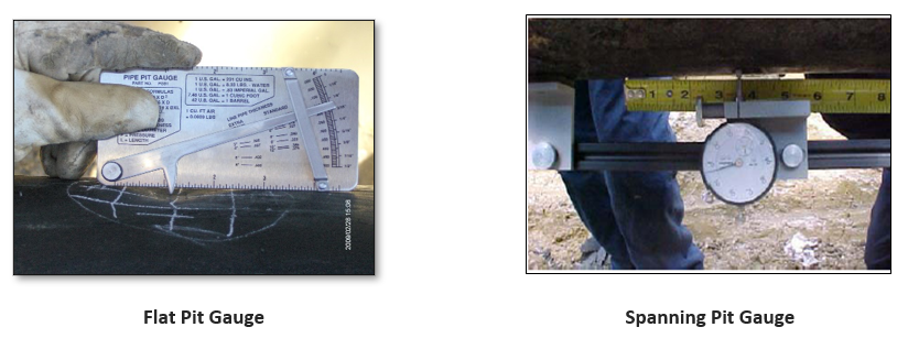
Common Field Type Mechanical Pit Gauges
The two (2) common types of mechanical pit gauges for measuring corrosion pitting on pipes are the flat and the bridging or spanning types. The flat pit gage has been around for at least 70 years doing Level 1 type pitting investigations for maximum depth and length on a single pit. However, for Level 2 evaluations which require more detailed pit depths and accuracies, new technologies such as the 3D tools are now needed.
- Time to Assess
- Slow and Methodical Process
- Error
- Common Field Measurements Can Vary from +-10%
- Dependent on Technicians Abilities
- Error-prone in every step
- Impact on corrosion analysis
- Safety
- Unnecessary cut-outs
- Economic
3D Tools to Assess Defect
There are two (2) basic types of 3D tools to measure corrosion pitting and other defects. 3D structured light and laser are the most common methods used.
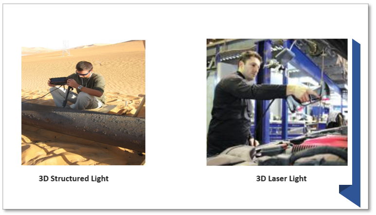
The advances in 3D structured light, also known as Phase Measurement Profilometry (PMP), have changed the dynamics of the industry. Combining this technology with advanced software using statistical analysis has produced better pipeline integrity predictions to meet the demands of safely transporting today’s energy products. Because of the limitations of the other pitting tools and methods, the 3D structured light approach offers the following benefits:
- Meets IP67 requirements (Can be dropped on concrete and or submerged/used underwater)
- Repeatability (Measure of performance each time)
- Speed – Takes photos similar to a 2D camera in less than 80 milliseconds (mS)
- Visual and digital records are produced immediately for assessment to meet regulatory requirements
- Immediate data is made available for assessments using ASME B31G, Modified ASME B31G, RSTRENG©, API 579/ASME FFS-1, statistical calculations, and stress-strain calculations for dents
- Internal error checking – on every pixel
- Accuracy – Less than 50.8 microns (2 mils)
ASME/API 579 FFS-1 (Level 1, 2 and 3)
Fitness for service has been used in the oil and gas industry since the early 1980s. On the petroleum industry side, it was always known as FFS, while on the gas pipeline side, it was known as ASME B31.G. In 2007 the American Petroleum Institute (API) and American Society of Mechanical Engineers (ASME) published a joint document as API RP 579-1/ASME FFS-1. This recommended practice (RP) consists of the following three levels for assessing corrosion:
- Level 1 – Quick evaluation with the minimum number of measurements (maximum depth and length) with a built-in large safety factor (ASME B31.G and Modified B31.G).
- Level 2 – Additional measurements and more in-depth analysis to establish a remaining strength of corroded pipe (RSTRENG).
- Level 3 – Intensive measurements using tools such as the 3D Toolbox – Phase Measurement Profilometry (PMP), loading, stresses, stress-strain, and material understanding to conduct a finite element analysis (FEA).
Because of the errors in the past using mechanical instrumentation (pit gauges) used in the past, rarely was a Level 3 analysis conducted. The field data was too inconsistent or too difficult to measure due to the complexity of the defects and features.
Factors for selecting a Level for analysis of a corroded area include:
- Quantity of data available with which to perform an evaluation
- Quality of the data
- The degree of significance of the analysis to the pipeline operations
- The degree of significance of a specific corroded area in the remedial plan for all anomalies in a line section being investigated
See Also: ASME B31G
Pit Gauges
See Also: Pit Gage Measurements
Industry Desires
New technologies should be evaluated and implemented as appropriate when older technologies are no longer meeting the safety and regulatory needs. In order to meet the requirements of TVC, traceable, verifiable, and complete in determining the effectiveness of an operator’s integrity management program, new technologies should be evaluated in order to continuously improve the integrity management program.
Significant Opportunities for Improvement Using 3D Structured Light
- Reduce or eliminate human factors from the measurement process
- Simple to use
- Increase speed
- Reduce cost
- Shorten the time from examination to decision
- Enhanced analysis solutions
- Exportable/useable data
- Permanent Reporting & Documentation
- Data collection to FFS answer in very short time
3D Analysis Approach
The first step in managing integrity is identifying potential threats to integrity. All threats to pipeline integrity shall be considered. A performance-based program through appropriate evaluation and analysis is used to determine courses of action and time frames for the application of the inspection tools. It is the responsibility of the operator to document the analyses justifying the alternate courses of action or time frames
Data and information from an inspection run for a specific threat is valuable when considering the presence of other threats. For example, a dent may be identified when ILI is run while assessing for corrosion. These threats should be integrated with other threats. Below is a listing of various threats that are found on pipelines.
- Arc Strike
- Artificial Defect
- Buckle
- Corrosion
- Corrosion Cluster
- Cracks -Visible
- Dent
- Dent with Metal Loss
- Gouging
- Grinding
- Girth Weld Crack
- Girth Weld Anomaly
- Hydrogen Induced Cracking
- Longitudinal Weld Crack
- Longitudinal Weld Pipe Mill Anomaly
- Pipe Mill Anomaly Cluster
- Stress Corrosion Cracking (SCC)
- Spiral Weld Crack
- Spiral Weld Anomaly
- Wrinkles
After the initial assessments have been performed, the operator needs to update information about the condition of the pipeline system or segment. This information is part of the TVC process and needs to be part of the database of information used to support integrity evaluations.
Examples of 3D Structure Light Measurements
The 3D Toolbox is a portable, field-ruggedized system for measuring and analyzing metal loss and mechanical damage on tanks, vessels, and pipes.
3D Toolbox
The process is a simple, four (4) step approach to meet the stringent regulatory requirements of TVC (Traceable, Verifiable, and Complete):
- Validate calibration
- Measure the 3D pipe features/defects using the 3D Camera
- Analyze the 3D features to identify features of interest
- Export data features for post-processing and reporting
- ASME B31.G, ASME B31.G Modified, and RSRTENG for corrosion
- ASME B31.8 and ASME B31.8 Modified for dents analysis
System Components
- 3D Camera
- Power Supplies and Adopters
- Cables
- Panasonic Toughbook
- Monopod
- Accessories (Batteries, Backpacks, Tripods, Tractors, etc.)
3D Structured Light Toolbox
- Measures surface defects (Length, Width, and Depth – X, Y & Z)
- Uses the Pipeline (PL) Analysis Tool for most common subsurface or above surface defects including welds
- Calculates remaining strength of corroded pipe (Level 1 and 2)
- Calculates the % Depth and Stress-Strain (Level 1 and 2)
- Produces Corrosion and Dent reports to meet regulatory requirements for TVC
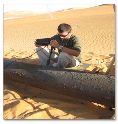
Below is a technician taking 3D scans of external corrosion in the Algerian Desert. 3D Structured Light can be used in a variety of ambient light conditions from ambient light to inside tanks or vessels.
Related Links
Section 4 Evaluating the Remaining Strength of Corroded Pipe