
Pull Force and Installation Stresses
The procedures for designing the bore path for plastic pipe are basically the same as discussed for steel pipe. As with steel product pipe, plastic pipe, when installed by HDD, may experience high-tension loads, severe bending, and external fluid pressures. HDD installation subjects the pipe to axial tensile forces caused by the frictional drag between the pipe and the borehole or drilling fluid, the frictional drag on the ground surface, the capstan effect around drill-path bends, and hydrokinetic drag. The pipe may also be subjected to external hoop pressures caused by the external fluid head and bending stresses. Estimating of pullback forces involves the assumption of many variables and installation techniques.
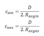
Estimated average radius of curvature at pipe entry and pipe exit:
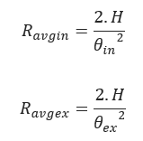
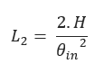
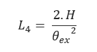
H – Depth of bore (ft)
Θin – Pipe entry angle (degree)
Θex – Pipe exit angle (degree)
L2 – Horizontal Distance to Achieve Desired Depth:
L4 – Horizontal Distance to Achieve Rise to the Surface:
L3 – Additional Distance Traversed at Desired Depth:
𝐿3 = 𝐿𝑐𝑟𝑜𝑠𝑠 − 𝐿2 − 𝐿4
Lcross – Length of the Crossing
Weight of Empty Pipe:
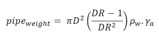
D – Pipe Diameter (inch)
DR – Pipe Dimension Ratio
ρw – Density of Water (lbf/inch3)
γa – Specific Gravity of Pipe Material
Average Weight of Empty Pipe:
𝑤𝑎 = 1.06 𝑝𝑖𝑝𝑒𝑤𝑒𝑖𝑔ℎ𝑡
Net Upward Buoyant Force on Empty Pipe:
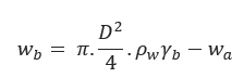
γb – Specific Gravity of the mud slurry
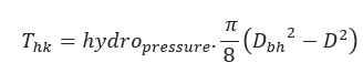
Hydrokinetic Force:
𝐷𝑏ℎ = 1.5.𝐷
Pull Force at point A:
𝑇1 = exp(𝜈𝑎𝜃𝑖𝑛)•[𝜈𝑎•𝑤𝑎(𝐿1 + 𝐿2 + 𝐿3 + 𝐿4)]
Pull Force at point B:
𝑇2 = exp(𝜈𝑎𝜃𝑖𝑛)•[𝑇1 + 𝑇ℎ𝑘 + 𝜈𝑏 • |𝑤𝑏| • 𝐿2 + 𝑤𝑏 • 𝐻 – 𝜈𝑎 •𝑊𝑎𝐿=exp(𝜈𝑎𝜃𝑖𝑛)]
Pull Force at point C:
𝑇3 = [𝑇2 + 𝑇ℎ𝑘 + 𝜈𝑏 •|𝑤𝑏|•𝐿3 – exp(𝑣𝑎•𝜃𝑖𝑛) • {𝜈𝑎𝑊𝑎𝐿3exp(𝜈𝑎𝜃𝑖𝑛)}]
Pull Force at point D:
𝑇4 = 𝑒𝑥𝑝(𝜈𝑏𝜃𝑒𝑥)[𝑇3 + 𝑇ℎ𝑘 + 𝜈𝑏•|𝑤𝑏|•𝐿4 – 𝑤𝑏•𝐻 – exp(𝑣𝑏𝜃𝑖𝑛) •{𝜈𝑎𝑊𝑎𝐿4exp(𝜈𝑎𝜃𝑖𝑛)}]
νa – Coefficient of Friction at the Surface
νb – Coefficient of Friction within Borehole
Bending Strain:
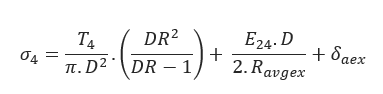
Bending Stress:
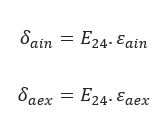
E24 = 24 hr-Apparent Modulus of Elasticity
Allowable Tensile Stress:
we
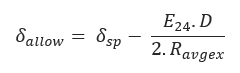
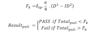
δsp – Allowable/Safe Pull Stress (psi)
Tensile Stress at Point A:
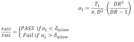
Tensile Stress at Point B:
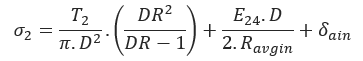
Tensile Stress at Point C:
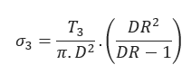
Tensile Stress at Point D:
Breakaway Links Settings:
Static Head Pressure:
𝑃𝑒𝑥𝑡 = 𝜌𝑤•𝛾𝑏•𝐻
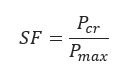
Maximum Pressure During Pullback:
𝑃𝑚𝑎𝑥 = 𝑃𝑒𝑥𝑡 + ℎ𝑦𝑑𝑟𝑜𝑝𝑟𝑒𝑠𝑠𝑢𝑟𝑒
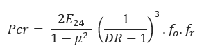
Ovality Compensation Factor:
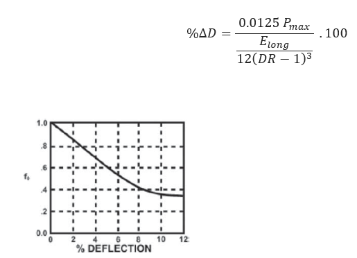
f0 – Ovality compensation factor based on % of Deflection (%Δ𝐷)
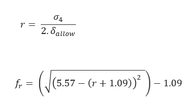
Tensile Reduction Factor:
Critical Collapse Pressure:
Safety Factor:
Input Parameters
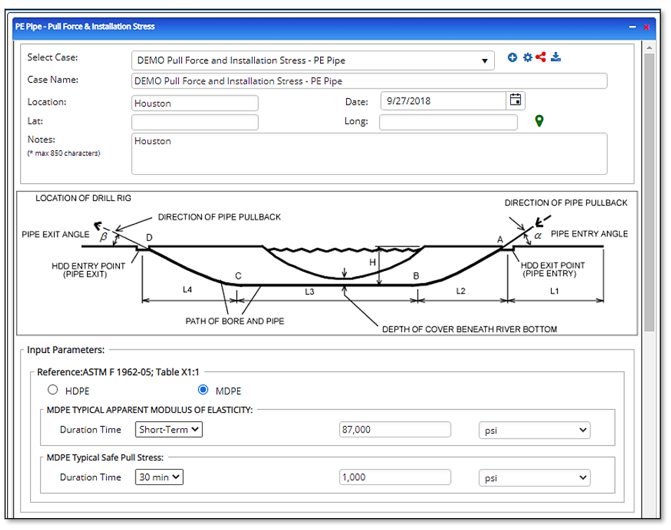
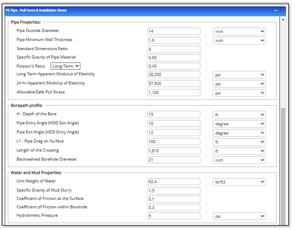
Pipe Properties:
- Pipe Outside Diameter (in)
- Pipe Minimum Wall Thickness (in)
- Standard Dimensions Ratio
- Specific Gravity of Pipe Material
- Poisson’s Ratio
- Long Term Apparent Modulus of Elasticity (psi)
- 24 hr-Apparent Modulus of Elasticity (psi)
- Allowable/Safe Pull Stress (psi)
- Percent of Pipe Ovality (%)
Borehole Path:
- H – Depth of the Bore (ft)
- Pipe Entry Angle (HDD Exit Angle) (degree)
- Pipe Exit Angle (HDD Entry Angle) (degree)
- L1 – Pipe Drag on Surface (ft)
- Length of the Crossing (ft)
- Backreamed Borehole Diameter (inch)
Water and Mud Properties:
- Unit Weight of Water (lb/ft3)
- Specific Gravity of Mud Slurry
- Coefficient of Friction at the Surface
- Coefficient of Friction within Borehole
- Hydrokinetic Pressure (psi)
Outputs/Reports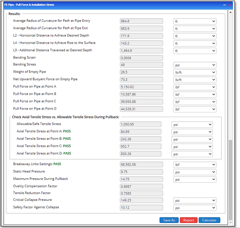
- Average radius of curvature for path at pipe entry (ft)
- Average radius of curvature for path at pipe exit (ft)
- L2 – Horizontal Distance to Achieve Desired Depth (ft)
- L4 – Horizontal Distance to Achieve Rise to the Surface (ft)
- L3 – Additional Distance Traversed at Desired Depth (ft)
- Bending Strain
- Bending Stress (psi)
- Weight of Empty Pipe (lb/ft)
- Net Upward Buoyant Force on Empty Pipe (lb/ft)
- Pull Force on Pipe at Point A (lb/ft)
- Pull Force on Pipe at Point B (lb/ft)
- Pull Force on Pipe at Point C (lb/ft)
- Pull Force on Pipe at Point D (lb/ft)
Check Axial Tensile Stress vs. Allowable Tensile Stress During Pullback:
- Allowable/Safe Tensile Stress (psi)
- Axial Tensile Stress at Point A (psi)
- Axial Tensile Stress at Point B (psi)
- Axial Tensile Stress at Point C (psi)
- Axial Tensile Stress at Point D (psi)
- Breakaway Links Settings (lbf)
- Static Head Pressure (psi)
- Maximum Pressure During Pullback (psi)
- Ovality Compensation Factor
- Tensile Reduction Factor
- Critical Collapse Pressure (psi)
- Safety Factor Against Collapse (psi)