
Introduction
When pipes are installed by HDD, they often experience high tension loads, severe bending, and external fluid pressures. Often these installation loads are more severe than the design service loads. When selecting the appropriate pipe materials for an HDD installation, the designer must consider the pipe properties as well as the borehole profile. These two factors should be considered together in order to choose the best material and profile so that the pipeline can be installed and operated without risk of damage. To ensure that the material and bore-hole profile are suitable for the proposed application, the installation, operational, and combined loads and stresses are analyzed.
Cables installed into conduits have installation parameters such as maximum pulling tensions, sidewall pressure, clearance, and jamming, which must be considered. Cable damaged during installation can cause service failures. Mechanical stresses during installation are generally more severe than those encountered while in service.
Cable Jamming

J = Jam Ratio
D = Inside Diameter of the Duct
d = Nominal Outside Diameter of One Cable (inch)
If 2.8 <= J<=3.0 jamming could occur, and it’s not recommended that the cable is pulled with this jam ratio
Clearance
Clearance is the distance between the top of the uppermost cable in the conduit and
the inner top surface of the conduit. It should be at least 10% of the conduit inner
diameter or one inch for large cables or installations involving numerous bends.
Equations for calculating clearance (CL) are presented as follows:
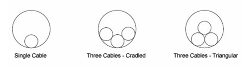
a) Single Cable Pull
C = D-d’
d’ = 1.05 d
b) There Cable Pull (Cradle Configuration)
![]()
c) Three Cable Pull (Triangular Configuration)
![]()
Weight Correction Factor
The configuration of cables can affect cable tension. A weight correction factor (Wc) is
used in the tension equations to account for this effect. The value for the weight correction factor is determined from the equations that follow:
a) Three Single Cables in Cradle Configuration
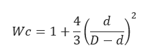
b) There Single Cables in Triangular Configuration
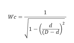
c) Single Cable in Conduit
Wc = 1
Wc = Weight Correction Factor
Cable Pull Tension Calculator
Tension at Point “B”
𝑇𝐵 = 𝑇𝐴 + 𝐿𝐴𝐵𝑊c(𝑠𝑖𝑛𝛼 – 𝐾𝑊𝐶𝑐𝑜𝑠𝛼)
𝑇𝐵 – Tension at point “B” (lbf)
𝐿𝐴𝐵 – Measure length of section “A-B” (ft)
a – Conduit pipe entry angle (ᵒ)
K – Dynamic coefficient of friction
Tension at Point “C”
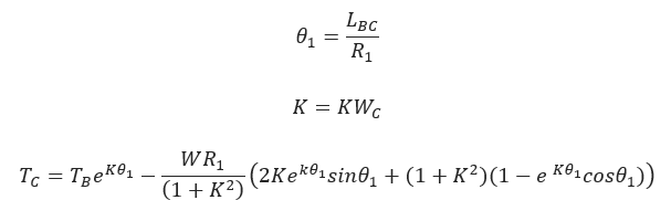
TC – Tension at point “C” (lbf)
θ1 – Angle measure from the vertical axis
LBC – Measure length of the curved section “B-C” (ft)
R1 – Radius of curvature (ft)
Tension at Point “D”
𝑇𝐷 = 𝑇𝐶 + 𝑊𝐶𝐾𝐿𝐶𝐷
𝑇𝐷 – Tension at point “D” (lbf)
𝐿𝐶𝐷 – Measure length for section “C-D”
Tension at Point “E”
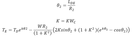
TE – Tension at point “E” (lbf)
θ2 – Angle measure from the vertical axis
LDE – Measure length of the curved section “B-C” (ft)
R2 – Radius of curvature (ft)
Tension at Point “F”
![]()
TF – Tension at point “F” (lbf)
LEF – Measure length of section “A-B” (ft)
β – Conduit pipe exit angle (ᵒ)
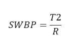
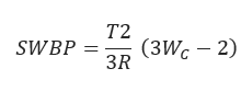
Sidewall Pressure
Sidewall Pressure (SP) is exerted on a cable as it is pulled around a bend. Excessive sidewall pressure can cause cable damage and is the most restrictive factor in many installations
a) Single Cable in Conduits
b) Three Cable in Conduit – Cradle Configuration
c) Three Cable in Conduit – Triangular Configuration
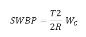
T2 = Tension at Bend Exit
Input Parameters
Cable Configuration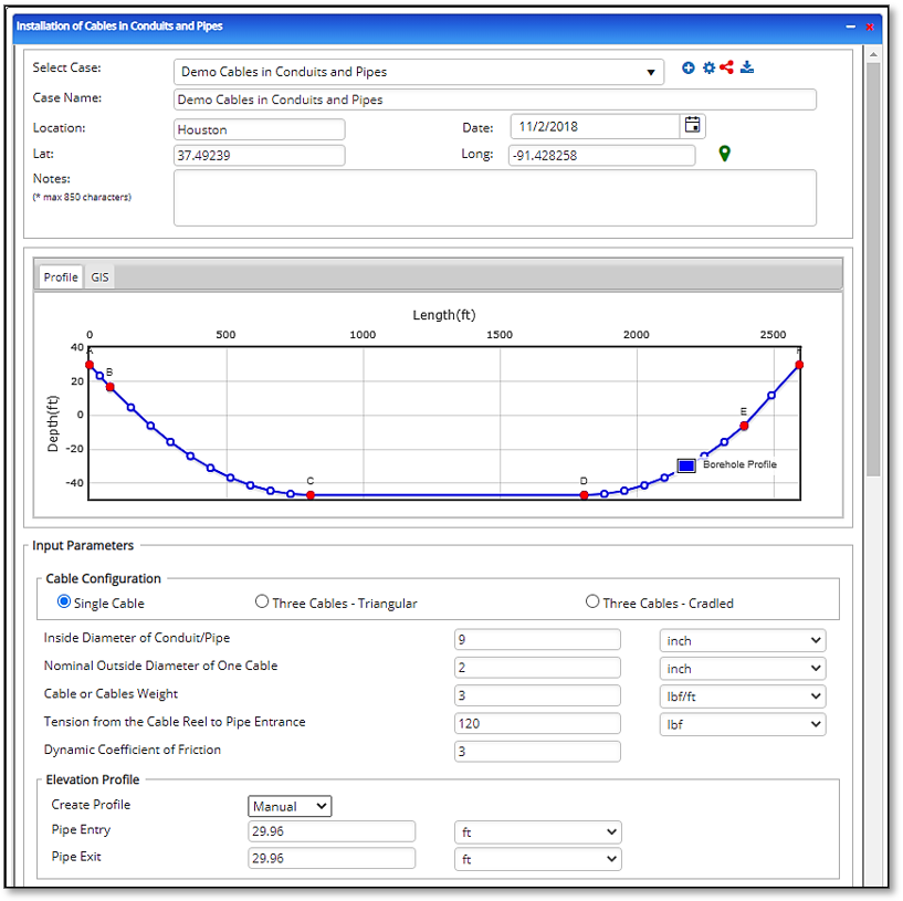
- Single Cable
- Three Cable – Triangular
- Three Cables – Cradled
Input Variable: Pipe, Cable, and Friction
- Inside Diameter of Conduit/Pipe (inch)
- Nominal Outside Diameter of One Cable (inch)
- Cable or Cables Weight (inch)
- Tension from the Cable Reel to Pipe Entrance (inch)
- Dynamic Coefficient of Friction (dimensionless)
- Create Profile (Shape, Excel, Manual)
- Pipe Entry (ft)
- Pipe Exit (ft)
Input Variable: Pipe Pulling Profile*: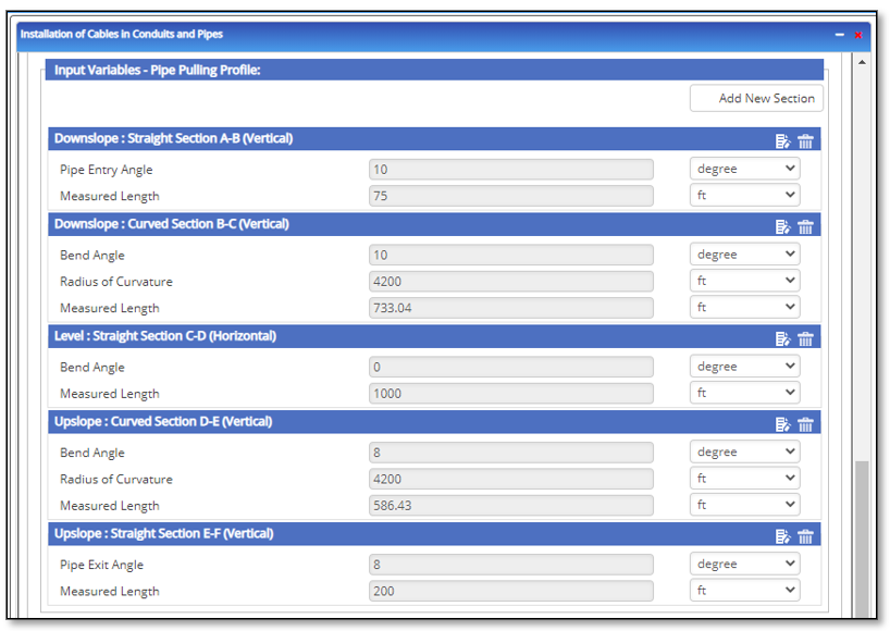
- Downslope: Straight Section A – B
- Pipe Entry Angle A – B [degree]
- Measured Length A – B [ft]
- Downslope: Curved Section B – C
- Bend Angle B – C [degree]
- Radius of Curvature B – C [ft]
- Straight Section C – D
- Horizontal Angle[degree]
- Measured Length [ft]
- Upslope: Curved Section D – E
- Bend Angle D – E [degree]
- Radius of Curvature [ft]
- Upslope: Straight Section E – F
- Pipe Exit Angle E – F [degree]
- Measured Length E – F [ft]
*The input entry varies depending on the number of sections added.
Outputs/Reports
- View the results.
- To SAVE, be sure to fill out all project details then click the SAVE button.
- To generate a REPORT, click the REPORT button.
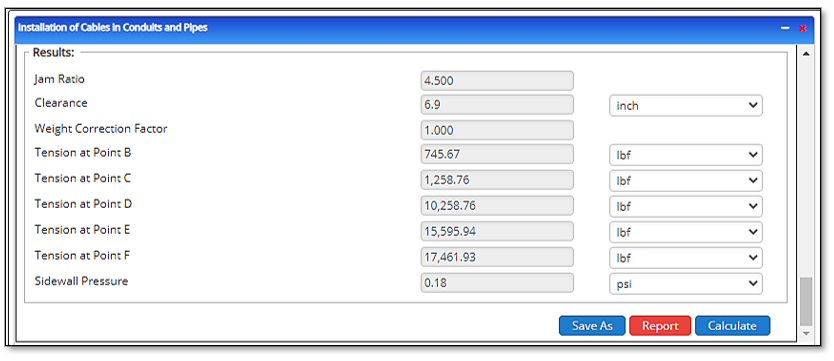
- Jam Ratio (dimensionless)
- Clearance (inch)
- Weight Correction Factor (dimensionless)
- Tension at Point B (lbf)
- Tension at Point C (lbf)
- Tension at Point D (lbf)
- Tension at Point E (lbf)
- Tension at Point F (lbf)
- Tension at Point G (lbf)
- Sidewall Pressure (psi)