
The AC Mitigation PowerTool© GIS version is designed to analyze unlimited pipeline and electric transmission tower lines to truly understand, model, and mitigate underground pipeline(s) with alternating (AC) induced current. The AC Mitigation PowerTool© has been developed to assist designers, engineers, and technicians to model and mitigate or modify the design of pipeline cathodic protection systems to reduce the AC current density effects to meet the criteria specified either by a client or the Association for Materials Protection and Performance (AMPP formally known as NACE) standard.
In high consequence areas (HCA’s), multiple underground facilities can run in and around the same right of way (R/W). Most of these utilities are known; however, some are unknown. Multiple rights of way with utilities such as water lines, natural gas lines, and oil and gas pipeline(s) all coexist to supply neighborhoods and businesses.
As demand for oil and gas increases, pipeline companies are installing new lines with fusion-bonded epoxy (FBE) coating technologies that prove very effective against normal DC corrosion. However, these newer FBE coatings have an unexpected corrosion threat from alternating current (AC) effects due to micro-holidays. Normally, these small defects are not a problem regarding cathodic protection; however, they become a threat when AC voltage and current densities increase under specific conditions with AC transmission lines located in the same right of way (R/W).
- This phenomenon may affect pipeline(s) placed in the same path as high voltage AC transmission towers. The electromagnetic effects affect the underground protective coating system where high AC load conditions occur along the line, causing the pipe to corrode due to inductive conditions.
- These conditions are a result of the type of soil present, its resistivity, distance or proximity from the tower, power line loads, the number of crossings, isolation of the pipeline, etc…
- AC corrosion’s detrimental effects are understood within the corrosion community and with pipeline operators. However, it requires field investigation, threat analysis, design, mitigation, validation, etc… to minimize the effects of AC induction to pipeline(s) from these power lines.
To respond to these AC corrosion threats, pipeline operators must develop an integrity management plan to prevent failure and implement these programs not only to comply with the safety regulations, but to provide asset preservation to the stakeholders.
- New and existing pipeline(s) co-existing with AC power line systems require pre-engineering analysis involving proximity assessments, DC and AC potential monitoring, interference testing, and related pipe investigation information.
- Once the threat of AC corrosion is identified, it should be followed up with AC corrosion modeling to assess the risks.
- AC mitigation modeling will ensure that the right plan of action is taken to prevent AC corrosion from becoming a threat to the pipeline’s integrity, pipeline operating personnel, and the public.
Objective
The ACPT User’s Manual presents information, guidelines, and procedures for use during assessment, modeling, mitigation, and monitoring corrosion on underground cathodically protected steel piping systems in proximity with alternating current (AC) power line systems. In addition, it is part of the Technical Toolboxes HUB system that incorporates ArcGIS as well as all other Technical Toolboxes software, such as the Pipeline Toolbox, RSTRENG+, HDD PowerTool, etc…
For additional information about AC interference and mitigation, please see the report that is furnished by Pipeline Research Council International, Inc. (PRCI) “PRCI PR-200-9414” on this link.
Methodology
The ACPT provides the user with a modeling tool to assess, design, mitigate or modify the design of pipeline cathodic protection systems to reduce the threat of AC current effects to a pipeline structure.
AMPP Understanding of AC Corrosion:
- AC current density leading to depolarization (>30 Am2)
- DC current density – Overprotection (>1Am2)
- Coating type, thickness, and resistance
- Soil resistivity
- Cathodic Protection
- Spread Resistance
AC corrosion criteria are contingent upon many factors, including DC current density. Therefore, AC and DC coupons play a significant role in the analysis versus the actual coating holiday sizes on the pipe. This can change the AC criterion up to 100 Am2. See Appendix D using coupon monitoring to measure AC and DC current densities.
If field measurements are used, the user must know the power line loading characteristics at the time of the survey or know the worst-case loading the transmission line may undergo. This requires knowledge of how the power transmission line(s) are operating daily, seasonally, under unusual power demands from customers, and when undergoing sub-station switching. Since it can be challenging and expensive to get this data from power companies, data loggers to monitor structure to electrolyte AC potentials are required at various times of the year to make these determinations.
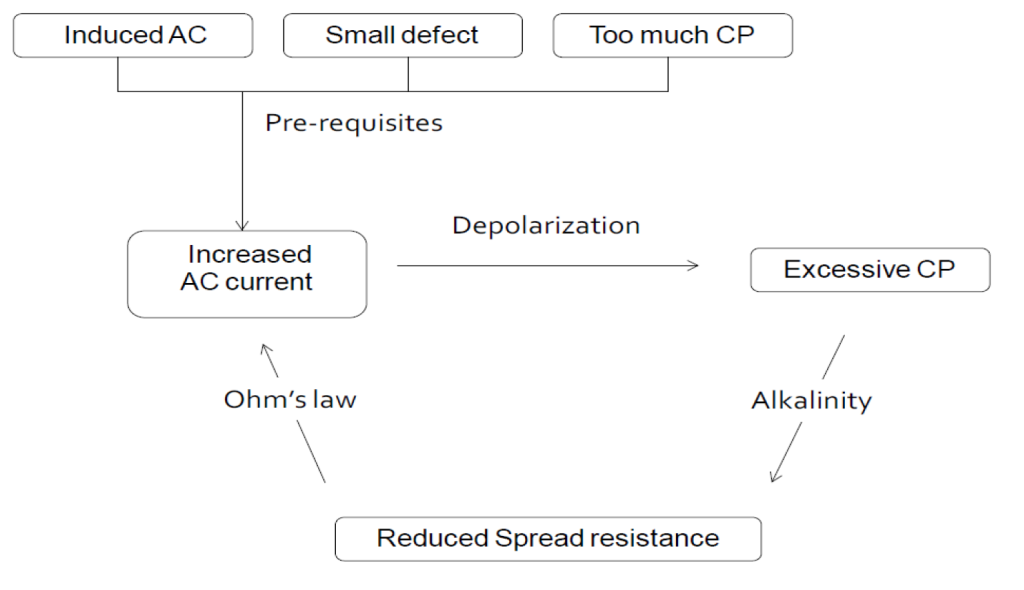
Below is diagram of AC corrosion on a cathodically protected pipeline to help in the understanding to this phenomenon. It shows the effects of induced AC (SS voltages), small defect and too much CP current and the result of reduced spread resistance resulting in AC corrosion.
Business Benefits
ACPT can address complex corridors and can assess unlimited pipeline(s) and high voltage transmission lines, as opposed to many other software solutions. It can also provide analysis for both steady state and fault current conditions. It has the capability to:
- Import KMZ, KML, Shape, and Excel files for both data integration into ArcGIS, computations, and data visualization.
- Integrated modeling can follow complex pipeline(s) and tower lines that are networked i.e. run parallel, diverge, or that intersect with each other.
- Multiple scenarios can be run with Steady State, Faults, and mitigation in minutes
- Combined or Individual graphs
- Ease of Excel import/export or manual data
- Can show data in total
- Data can be visualized
- Cloud or desktop version
- Detailed reports show graphs with data
- Export/Import data at any phase of the project
- Data validation and error checking
- Depth of cover for each section
- Barnes layers (Bulk Soil Resistivity) for each section
- Integration with the Technical Toolboxes HUB and ArcGIS
Module/Applications
References
- PR-200-9414 AC Predictive and Mitigation Techniques – Final Report
- SP0177-2019 Mitigation of Alternating Current and Lightning Effects on Metallic Structures and Corrosion Control Systems
- NACE 35110 State of the Art on AC Considerations
- NACE Technical Committee Report, “Mitigation of Alternating Current and Lightning Effects on Metallic Structures and Corrosion Control Systems”
FAQ
-
Does ACPT Assess AC and DC Transit System Interference?
Interference voltages and currents from AC and DC dynamic stray power traction systems are not assessed with the ACPT software. This is a question that has been asked multiple times by engineers over the years. The primary reason is interference pickup and leakage currents occur from the tracks to ground as the train moves station to station versus from low voltage power systems. Check Out
-
AC Power Tool (ACPT) Validation?
This is a validation of the Technical Toolboxes ACPT compared to the PRCI model developed by Dr. John Dabkowski. The is a focus study and validation. The data inputs that are recommended for consideration in this type testing as listed below. Check Out
-
ACPT and ACPTGIS versus PRCI AC Mitigation Angles?
ACPT/ACPTGIS uses bearing angles and extends the reference line(s) to come up the intersecting angles with other facilities such as powerlines and pipelines. Check Out
-
ACPT GIS Steady State – Creating Section Lines
Example of a map kmz. or kml. file was imported for both the Power Transmission Line and Pipeline as shown below. Then point and click technology is used to create sections at nodes, towers, proposed mitigation sites, soil resistivity changes, transpositions, etc. Check Out
-
ACPT – Methods Of Soil Resistivity (Barnes Layers)?
Barnes layer data are set up to represent the bulk soil multiple layers for the corrosive layer (pipe depth), deep layer (steady state and inductive fault) and conductive layer (conductive fault). Check Out
-
Fault Current Distribution X/R versus Combined Magnitude?
When a pipeline is located in the vicinity of a power line, it is subject to several electrical effects depending upon the operational status of the line. When a wire carries an electrical current, a magnetic field is produced around the wire which links the buried pipe. Check Out
-
Why the differences in All versus the Closest Tower?
ACPT Fault calculations allow the user to select ALL or a Specific Tower to assess the voltage across coating and the current on the pipe. Why the differences?
- Selecting the closest tower to pipeline results in a more accurate assessment of the fault to the pipeline
- Selecting ALL towers results in a general pattern of the voltages and currents across the length of each segment being assessed. Check Out
-
Estimating AC Voltages and Maximum Current on Power Lines?
The number of data inputs regarding Power Transmission Lines is approximately 25 for Steady State and Fault results. What does this mean is there are infinite combinations that could be run. However, most of them are default values; however, rarely does the client use these default values. Check Out
Definitions
- AC Corrosion
- Corrosion initiated and propagating under the influence of alternating current.
- AC Current Density (JAC)
- Unit: A/m2. The AC current density in a coating defect or in a coupon or probe used to simulate a coating defect of a certain area.
- AC Exposure
- Alternating voltages and currents induced on a structure because of the AC power system.
- AC Power Structures
- The structures associated with AC power systems.
- AC Power System
- The components associated with the generation, transmission, and distribution of AC.
- AC-Voltage (UAC)
- Unit: V. Voltage measured. The difference in AC potential between the pipeline and remote earth. The AC voltage is the ultimate driving force for the AC current density at a coating defect – which may cause corrosion – or the AC current density at grounding devices (including galvanic anodes) installed for mitigation purposes. The AC voltage is not a constant value since:
It will change over time primarily due to intermittent conditions in the AC power system, for instance, because household power consumption is different during daytime and nighttime.
It will change along the length of the pipeline since the induced voltage depends on the characteristics of the pipeline, characteristics of the interfering AC power system, as well as geometrical and geographical alignment.
- Affected Structure
- Pipes, cables, conduits, or other metallic structures exposed to the effects of AC or lightning.
- ArcGIS
- A geographic information system for working with maps and geographic information maintained by Esri.
- Bond
- A low-impedance connection (usually metallic) provided for electrical continuity.
- Breakdown Voltage
- A voltage in excess of the rated voltage that causes the destruction of a barrier film, coating, or other electrically isolating material.
- Capacitive Coupling
- The influence of two or more circuits upon one another, through a dielectric medium such as air, by means of the electric field acting between them
- Coating Stress Voltage (AC Voltage With Respect To Close Earth)
- Unit: V. Difference in AC potential between the metallic surface of a coated structure and the earth in contact with the outer surface of the coating. Circuit theory and computer simulations suggest that the coating stress voltage is technically more accurately, the driving force for the AC current density at coating defects when AC mitigation in the form of ribbon anodes installed in the proximity of the coating defect.
- DC Current Density
- Unit: A/m2. Refers to the DC current density a coating defect or a coupon or probe used to simulate a coating defect of a certain area.
- Direct Current (DC) Decoupling Device
- A device used in electrical circuits that allows the flow of AC in both directions and stops or substantially reduces the flow of DC.
- Earth Current
- Electric current flowing in the earth.
- Electric Field
- One of the elementary energy fields in nature. It occurs in the vicinity of an electrically charged body.
- Electric Potential
- The voltage between a given point and a remote reference point.
- Electrolytic Grounding Cell
- A device consisting of two or more buried electrodes installed at a fixed spacing, commonly made of zinc, and resistively coupled through a prepared backfill mixture. The electrical characteristics of a grounding cell include a small degree of resistance and a subsequent reduced voltage drop across the cell during a fault condition.
- Excessive Cathodic Protection (CP)
- Cathodic protection levels that lead to cathodic protection DC current densities exceeding 1 A/m2 or cathodic protection levels that lower the spread resistance due to cathodic reactions.
- Fault Current
- A current that flows from one conductor to ground or to another conductor due to an abnormal connection (including an arc) between the two. A fault current flowing to ground may be called a ground fault current.
- Gradient Control Mat
- A system of bare conductors connected to the affected structure and placed on or below the surface of the earth, usually at above grade or exposed appurtenances, arranged and interconnected to provide localized touch-and-step voltage protection. Metallic plates and gratings of suitable area are common forms of ground mats, as well as conventional bare conductors closely spaced.
- Gradient Control Wire
- A continuous and long grounding conductor or conductors installed horizontally and parallel to the affected structure at strategic lengths and connected at regular intervals to provide protection to the structure and coating during steady-state and fault AC conditions from nearby electric transmission power systems.
- Ground
- An electrical connection to earth.
- Ground Current
- Current flowing to or from earth in a grounding circuit.
- Ground Electrode Resistance
- The ohmic resistance between a grounding electrode and remote earth.
- Grounded
- Connected to earth or to some extensive conducting body that serves instead of the earth, whether the connection is intentional or accidental.
- Grounding Grid
- A system of grounding electrodes consisting of interconnected bare conductors buried in the earth to provide a common electrical ground.
- Guarded
- Covered, fenced, enclosed, or otherwise protected by means of suitable covers or casings, barrier rails or screens, mats, or platforms; designed to limit the likelihood, under normal conditions, of dangerous approach or accidental contact by persons or objects.
- Inductive Coupling
- The influence of two or more circuits upon one another by means of changing magnetic flux linking them together.
- Interference
- Any electrical disturbance on a structure because of stray current.
- Lightning
- An electric discharge that occurs in the atmosphere between clouds or between clouds and the earth.
- Load Current
- The current in an AC power system under normal operating conditions.
- Magnetic Field
- One of the elementary energy fields in nature. It occurs in the vicinity of a magnetic body or current-carrying medium.
- ON Potential
- (Eon) Unit: V. DC potential measured between the pipeline and a reference electrode placed in the adjacent soil while the cathodic protection current is flowing. This potential includes IR voltage drops in the soil. (IR drops).
- Over-Voltage Protector (Surge Arrester)
- A device that provides high resistance to DC and high impedance to AC under normal conditions within the specified DC and AC threshold rating and “closes” or has a very low resistance and impedance during upset conditions.
- Reclosing Procedure
- A procedure that normally takes place automatically whereby the circuit breaker system protecting a transmission line, generator, etc., recloses one or more times after it has tripped because of abnormal conditions such as surges, faults, lightning strikes, etc.
- Reference Electrode
- An electrode whose open-circuit potential is constant under similar conditions of measurement, which is used for measuring the relative potentials of other electrodes.
- Remote Earth
- A location on the earth far enough from the affected structure that the soil potential gradients associated with currents entering the earth from the affected structure is insignificant.
- Resistive Coupling
- The influence of two or more circuits on one another by means of conductive paths (metallic, semi-conductive, or electrolytic) between the circuits.
- Shock Hazard
- A condition considered to exist at an accessible part in a circuit between the part and ground or other accessible parts, if the steady-state open-circuit AC voltage is 15 V or more (root mean square [rms]). For capacitive build-up situations, a source capacity of 5 mA or more is recognized as a hazardous condition. For short circuit conditions, the permissible touch-and-step voltages should be determined in accordance with the methodology specified in accordance with IEEE(1) Standard 80.
- Solid-State DC Decoupler
- A dry type of DC decoupling device comprising solid-state electronics. The electrical characteristics of a solid-state decoupler are high resistance to low voltage DC and low impedance to AC.
- Spread Resistance (SR)
- Unit: Ω∙m2. Refers to the resistance from the pipe to earth through a specific coating defect with known area, or the resistance from a coupon or probe with a known exposed area, to earth. The spread resistance multiplied by the DC current density constitutes the voltage drop (IR) and the spread resistance is a factor proportionality between AC voltage and AC current density.
- Step Potential or Voltage (V)
- The potential difference between two points on the earth’s surface separated by a distance of one human step, which is defined as one meter, determined in the direction of maximum potential gradient.
- Stray Current
- Current flowing through paths other than the intended circuit.
- Surface Potential Gradient
- Change in the potential on the surface of the ground with respect to distance.
- Touch Potential or Voltage (V)
- The potential difference between a metallic structure and a point on the earth’s surface separated by a distance equal to the normal maximum horizontal reach of a human (approximately 1.0 m [3.3 ft]).
- Voltage (V)
- The difference in electrical potential between two points.