
Introduction
Movement of in-service Pipelines is calculated to conform elastically to a given trench profile. Longitudinal Stress due to bending/elongation and elastic curvature must be considered.
Total Longitudinal Stress
The total longitudinal stress in the pipe can be estimated with the following equation: S_L=S_E+S_B+S_S
S_L=S_E+S_B+S_S
Where:
𝑆𝐿 = Total Longitudinal Stress in the Pipe (psi)
𝑆𝐸 = Existing Longitudinal Stress in the Pipe (psi)
𝑆𝐵 = Longitudinal Stress in the Pipe due to Bending caused by Movement Operation (psi)
𝑆𝑆 = Longitudinal Stress in the Pipe due to its Elongation caused by the Movement Operation (psi)
Longitudinal Tensile Stress Due To Internal Pressure
The longitudinal tensile stress in the pipe due to internal pressure may be estimated with the following equation: S_P=\frac{PD\mu}{2t}
S_P=\frac{PD\mu}{2t}Where:
𝑆𝑃 = Longitudinal Tensile Stress in the Pipe due to Internal Pressure (psi)
𝑃 = Maximum Internal Operating Pressure of the Pipe (psi)
𝐷 = Outside Diameter of the Pipe (in)
𝜇 = Poisson′s Ratio for Steel − (0.3)
𝑡 = Nominal Wall Thickness of the Pipe (in)
Longitudinal Tensile Stress Due To Temperature Change
The longitudinal tensile stress in the pipe due to a change in the temperature may be estimated with following equation: S_r=E\alpha(T_1-T_2)
S_r=E\alpha(T_1-T_2)
Where:
𝑆𝑟 = Longitudinal Tensile Stress in the Pipe due to Change in Temperature (psi)
𝐸 = Modulus of Elasticity of Steel − 29×106
𝛼 = Linear Coefficient of Thermal Expansion for Steel − 6.5×10⁻⁶ (in/℉)
𝑇1 = Temperature of the Pipe at Installation (℉)
𝑇2 = Operating Temperature of the Pipe during Movement (℉)
*If the pipe’s temperature at installation time is not known, it should be reasonably estimated*
Longitudinal Flexure Stress Due To Existing Elastic Curvature
When a pipeline is laid to conform elastically to a given trench profile, the pipeline will experience induced flexural stress in amount proportional to its curvature. In hilly terrain, where slopes are unstable, or where soils are subject to frost heave or liquefaction, the pipeline is likely to experience stress of unpredictable and varying magnitude. This stress 𝑆𝐶 )can range from near-yield-strength levels in tension to near-bulking levels in compression. This existing stress should be considered prior to a movement operation.
Existing Longitudinal Stress
The existing longitudinal stress in a pipeline will normally be in the range of-10,000 psi to 20,000 psi. In the flat or gently rolling terrain where soils are not subject to frost heave or liquefaction, the pipeline will experience only the longitudinal tensile stress due to internal pressure and temperature as discussed above. The existing longitudinal stress in the pipe may be estimated
With following equation: S_E=S_p+S_r+S_c
S_E=S_p+S_r+S_c
Where:
𝑆𝐶 = Longitudinal Tensile Stress in the Pipe due to Existing Elastic Curvature (psi)
Longitudinal Stress Due To Bending
The longitudinal stress in the pipe due to bending may be estimated with following equation: S_B=\frac{w_rL_I^2}{12S}
S_B=\frac{w_rL_I^2}{12S}Where:
𝑤𝑟 = Net uniformly distributed load required to achieve the desired mid-span vertical deflection of the pipe (not full weight of the pipe and fluid) (psi)
𝐿𝐼 = Minimum trench length required to reach the mid-span vertical deflection of the Pipe (in)
𝑆 = Elastic section modulus of the pipe (in)
Longitudinal Stress Due To Elongation
The longitudinal stress in the pipe due to elongation caused by the movement operation may be estimated with the following equation: S_S=2.67E\left( \frac{\Delta}{L}\right)^2
S_S=2.67E\left( \frac{\Delta}{L}\right)^2Where:
Δ = Mid-span deflection of the pipe, (ft)
𝐿 = Minimum trench length required to reach the mid-span deflection of the pipe Δ (ft)
*The effects of this stress may be offset by an elastic compressive stress existing in the pipeline prior to the moving because of slack*
Available Longitudinal Bending Stress
The longitudinal stress available for bending may be estimated with the following equation: S_A=F_DSMYS-S_E-S_S
S_A=F_DSMYS-S_E-S_S
Where:
𝑆𝐴 = Longitudinal stress available for bending (psi)
𝐹𝐷 = Design Factor
SMYS = Specific Minimum Yield Strength (psi)
Trench Length
The minimum trench length required to achieve a mid-span deflection of the pipe without exceeding the longitudinal stress limit can be determined with the following equation, based on elastic free deflection theory, which treats the pipe as a single-span beam that is fixed at both ends and that has a uniformly distributed load: L = \sqrt{\frac{(3.87 \times 10^7) D\Delta (7.74 \times 10^7) \Delta^2}{F_D SMYS – S_E}}
L = \sqrt{\frac{(3.87 \times 10^7) D\Delta (7.74 \times 10^7) \Delta^2}{F_D SMYS - S_E}}
Trench (Or Displacement) Profile
A profile for the moved portion of the pipeline should be designed to minimize induced bending stress concentrations. Therefore, to obtain acceptable longitudinal stress distribution due to bending, the deflection at any point along the trench profile can be determined with the following equation: \Delta_x = \frac{16X^2 \Delta (L – x)^2}{L^4}
\Delta_x = \frac{16X^2 \Delta (L - x)^2}{L^4}
Where:
Δ𝑥 = Vertical Deflection of the Pipe at Distance x (ft)
L = longitudinal stress available for bending (psi)
𝑥 = Distance along the length of the trench from the starting point of the pipe deflection (ft)
Supporting Spacing
Based on a four-span, uniformly loaded beam, the maximum free span between supports can be determined with the following equation: L_s = \sqrt{\frac{0.0286S_A (D^4 – d^4)}{D^3 – 0.8724d^2D}}
L_s = \sqrt{\frac{0.0286S_A (D^4 - d^4)}{D^3 - 0.8724d^2D}}
Where:
𝐿𝑆 = Maximum Free Span Between Pipe Supports (ft)
𝑑 = Inside Diameter of the Pipe (in)
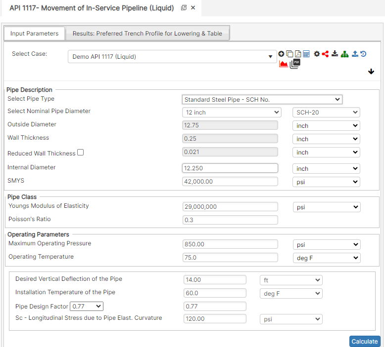
Case Guide
Part 1: Create Case
- Select the API 1117 – Movement of In-Service Pipeline application from the PLTB Misc. Module
- To create a new case, click the “Add Case” button
- Enter Case Name, Location, Date and any necessary notes.
- Fill out all required Parameters.
- Make sure the values you are inputting are in the correct units.
- Click the CALCULATE button to overview results.
Input Parameters
- Nominal Pipe Size
- Outside Pipe Diameter (in)
- Pipe Wall Thickness (in)
- Internal Pipe Diameter (in)
- Specified Minimum Yield Strength (psi)
- Modulus of Elasticity of Steel (psi)
- Poisson’s Ratio for Steel
- Maximum Operating Pressure (psi)
- Operating Temperature of the Pipe (°F)
- Desired Vertical Deflection of the Pipe (ft)
- Installation Temperature of the Pipe (°F)
- Pipe Design Factor
- Sc – Longitudinal Stress due to Pipe Elasticity Curvature (psi)
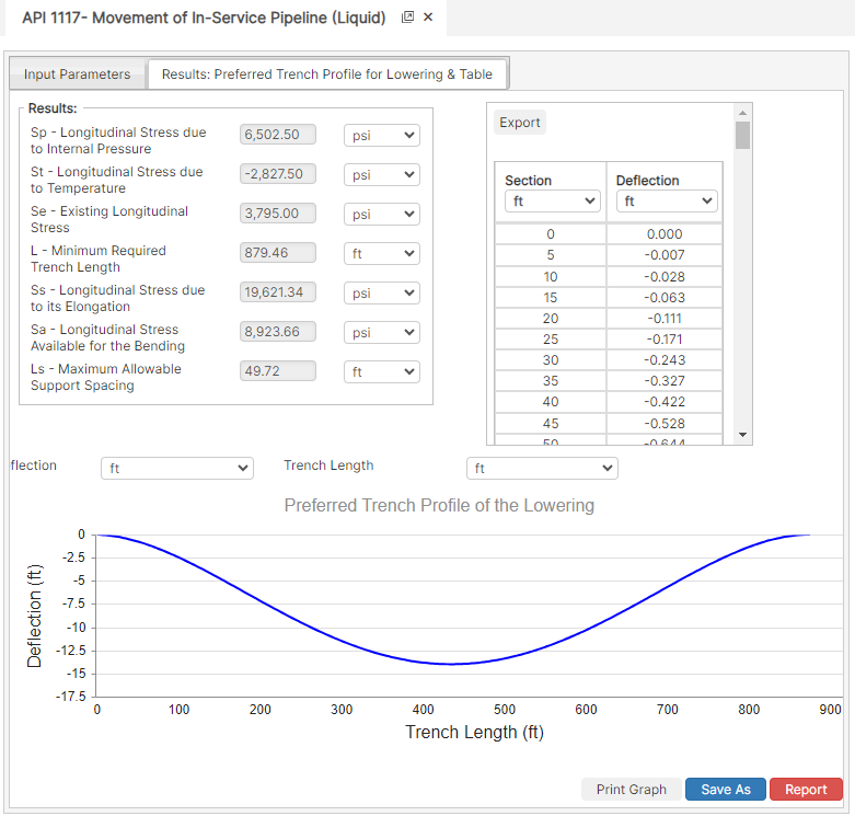
Part 2: Outputs/Reports
- If you need to modify an input parameter, click the CALCULATE button after the change.
- To SAVE, fill out all required case details then click the SAVE button.
- To rename an existing file, click the SAVE As button. Provide all case info then click SAVE.
- To generate a REPORT, click the REPORT button.
- The user may export the Case/Report by clicking the Export to Excel icon.
- To delete a case, click the DELETE icon near the top of the widget.
Results
- Sp – Longitudinal Stress due to Internal Pressure (psi)
- St – Longitudinal Stress due to Temperature (psi)
- Se – Existing Longitudinal Stress (psi)
- L – Minimum Required Trench Length (ft)
- Ss – Longitudinal Stress due to its Elongation (psi)
- Sa – Longitudinal Stress Available for the Bending (psi)
- Ls – Maximum Allowable Support Spacing (ft)
- Deflection (ft)
- Trench Length (ft)
References
- API 1117 – Recommended Practice for Movement of In-Service Pipelines