
Introduction
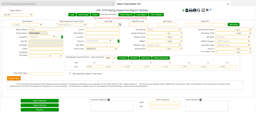
The API 570 Inspection Report Builder is a comprehensive tool designed to facilitate the development of detailed inspection reports for piping systems in accordance with API 570 Piping Inspection Code. This guide provides structured instructions on data entry, evaluation, calculations, and report compilation.
Users can access various sections and perform calculations, corrosion monitoring, AutoCAD drawings, checklists, and inspection write-ups. Each section follows a step-by-step methodology ensuring accuracy and compliance with industry standards.
Accessing the Tool
To access the API 570 Inspection Report Builder, follow the steps outlined below for initial setup, data entry, and report preparation:
Opening the Report Builder
- Navigate to the API 570 Inspection Module
- From the front page, select [API 570 Pipe Insp.].
- Click the [Report Builder] button at the bottom of the page.
- Selecting or Creating a Report
- To create a new report: Click New Report [+].
- To open an existing report: Use the “Select Report” dropdown menu and choose from the available reports.
- Entering Report Details for a New Report
- Input a unique “Report No.”
- Select the appropriate Unitset in the upper right-hand corner (US, Metric, or other).
- Enter all numerical data in accordance with the selected units, without signifiers (e.g., enter 1550 instead of 1550 psi for Design Pressure).
Data Entry and Validation
- Understanding Key Data Fields
- The Age/Prev Insp. field represents a numerical value, not a date (e.g., 9, 20, 34, etc.).
- This value is essential for corrosion rate calculations and must be accurately paired with the Nominal Thickness entry.
- Utilizing Pull-down Menus and Custom Entries
- Fields with [*] buttons allow users to add new entries for dropdown selections (e.g., Inspector, Service).
- These new entries will expand the database for future reports.
- Certain user-submitted entries will be flagged for review by the development team before being integrated into the universal database to maintain technical accuracy and compliance with national standards (e.g., material stress values, product data values).
- Quick Access to Codes & Standards
- A PDF Codes/Standards library is accessible at the top of the form for quick reference to official regulations and system-entered codes.
Managing Cover Text and Saving Data
- Cover Text Auto-population
- Initially, the cover text is auto-filled using data from the front page.
- Before first saving, the cover text will continue to update automatically.
- After the first save, the cover text becomes manual entry only, requiring users to manually edit any changes.
- Saving Data
- Always click the save icon before navigating to another page to prevent data loss.
- Spell Check Functionality:
- Right-click any redlined text for spelling corrections.
API and ASME Classification for Piping Systems
API-570 Pipe Service Classifications
- Class 1 Services (Highest Risk of Emergency in Case of Leak)
- Flammable services that can auto-refrigerate, leading to brittle fracture.
- Pressurized services that can rapidly vaporize, forming explosive mixtures (e.g., C2, C3, C4 streams).
- Gaseous streams containing Hydrogen Sulfide >3% weight.
- Anhydrous Hydrogen Chloride.
- Hydrofluoric Acid.
- Piping over or adjacent to water and public throughways (compliance with DOT and U.S. Coast Guard regulations).
- Class 2 Services (Standard Process & Off-Site Piping)
- Hydrocarbons that slowly vaporize upon release (e.g., operating below flash point).
- Hydrogen, fuel gas, and natural gas.
- Strong acids and caustics used on-site.
- Class 3 Services (Flammable, Non-Volatile, and Remote Hazards)
- Hydrocarbons that do not significantly vaporize upon release (below flash point).
- Distillate and product lines to/from storage and loading.
- Off-site acids and caustics.
ASME B31.3 Pipe Service Categories
- Category D Fluid Service
- Non-flammable, non-toxic, and not hazardous to human tissue.
- Pressure ≤ 150 psi and temperature ≤ 366°F.
- Category M Fluid Service
- Highly hazardous fluids, where even small leaks can cause irreversible harm via inhalation or bodily contact.
- Normal Fluid Service
- Any fluid service not classified under Category D or M and not in high-pressure or cyclic conditions.
Pipe/Nozzle Practical Tmin Table
- Displays default program values for practical minimum thickness (tmin).
- Users can manually override values to reflect real-world conditions.
- These values affect calculations throughout the report.
Preview, Printing, and Report Duplication
Limited Preview vs. Full Report Print
- Limited Preview:
- Prints the first four pages in PDF or Word format.
- Access using the printer icon with no designation.
- Full Report Print:
- Includes all developed appendices.
- For PDFs: Includes all attached PDF files, fully assembled in appendix order.
- Access using the printer icon with “F” designation.
Copying Reports for Editing
- If multiple reports share common information, use [Copy Report] to duplicate a report.
- The copied report will include:
- Front-page data
- Report write-up
- Appendices are NOT copied and must be re-entered.
Adding Company Logos and Signatures
- Company Logo
- Click the [Logo] button at the top of the form.
- Each report requires a separate logo upload (not global).
- Save a copy of the logo under My Documents → “AA Toolbox Support” for quick access.
- Inspector’s Signature
- Click the [Signature] button at the bottom of the form.
- Each report requires a separate signature upload.
Report Sharing and Ownership
- Viewing Shared Reports
- Click the group icon (5 people standing) to view shared access.
- Sharing a Report
- Click the linked dots icon.
- Select the person to share with.
- Click [Share], then [Close].
- Transferring Report Ownership
- Share the report using the above steps.
- Select the new owner from the dropdown.
- Click [Make Owner].
Downloading/Uploading Field Data Sheets
Downloading Templates
- Click “Download template” at the top of the Report Base Page.
- Open the file (Excel for data entry, Word for checklist).
- Save a local copy for the inspection project.
Uploading Field Templates
- Click [Import] at the top of the Report Base Page.
- Select the Excel template file and import.
- Click Save to update the cover text with the imported data.
- Review and fill in missing details (e.g., Logo, Inspector of Record, Appendices, Write-Up).

Sharing and Ownership of Reports
- To view shared access, click the group icon (with five people).
- To share a report, the owner must click the linked dots icon and select a user. Use the [Share] button to grant access or the [Make Owner] button to transfer ownership.
- Shared users can view but not edit the report, except for certain appendix functions.
Downloading/Uploading Field Data Sheets
- Downloading Templates: At the top of the Report Base Page, click the [Download Template] link to download Excel and Word templates for data entry and checklists. Save these files in the project folder for the inspection.
- Uploading Templates: After completing the templates, click the [Import] button at the top of the Report Base Page. Select the completed template file and click [Import File] to upload the data into the report.

Saving, Printing, and Copying Reports
- Saving Progress: Always click the [Save] icon before navigating away from the page to ensure no data is lost.
- Printing Options:
- Limited Preview: To print only the first four pages, click the printer icon without a designation.
- Full Report: To print the full report, including appendices, click the printer icon with the “F” designation and select either PDF or Word format.
- Copying Reports: Click on the [Copy Report] button to duplicate an existing report. Enter a new name for the copied report. Note that appendices are not copied and must be created separately.
Once imported, save the report to update the cover text and review or complete any remaining sections.
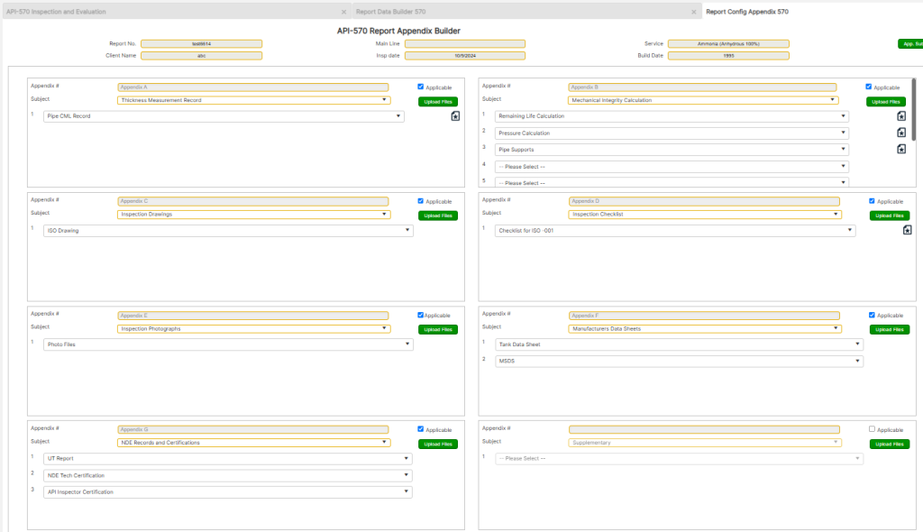
Report Configuration / Appendix
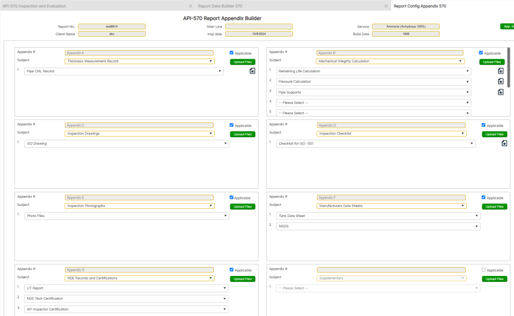
The Report Configuration / Appendix section allows users to manage additional report components that supplement the primary inspection findings. It provides a structured format for organizing appendices, additional calculations, AutoCAD drawings, inspection photographs, and checklists related to the API 510 inspection.
Accessing Report Configuration / Appendix
- From the front page, choose [API 510 PV Insp.]
- Click on [Report Builder] at the bottom of the page.
- Select an Existing Report from the drop-down menu.
- Click on the [Report Config. / Appendix] button at the bottom left.
Managing Report Appendices
- The Report Appendices will automatically populate with the most common appendix subjects associated with an API-510 inspection.
- The system divides the Report Configuration section into separate windows for building and modifying the report appendices.
- Users should progress from left to right (and Appendix A to H) when entering data in sub-forms, as the system cascades information through the reporting process.
Editing Default Appendix Text
- The default text in each appendix serves as a template and should be edited to reflect the actual inspection details.
- Users can either:
- Modify the default text to match the inspection.
- Delete the default text and enter new information as needed.
Adding or Removing Appendix Subjects
- Each data cell in the appendix contains a pull-down menu for selecting relevant inspection details.
- Users can add more subjects by clicking the [App. Subject] or [App. Text] buttons.
- To remove a text entry, click the pull-down arrow next to the text of interest and select “Please Select”.
- If an entire appendix is not applicable to the report, uncheck the “Applicable” checkbox in the upper-right corner of the appendix window.
Saving and Refreshing Changes
- To apply new additions or edits:
- Click the [Add New Subject/Text] button after entering the information.
- Click the Refresh Icon (two circular arrows in the upper-right corner) to update and display the newly added data.
- To return to the Report Base Page, click the back arrow in the upper-right corner.
Final Steps and Navigation
- Saving Progress: Always click the Save icon before navigating away from any page to ensure that data and changes are not lost.
- Returning to the Base Page: To move back to the Report Base Page, click on the back arrow in the upper-right corner of the screen.
Report Component Corrosion Monitoring location (CML) Record
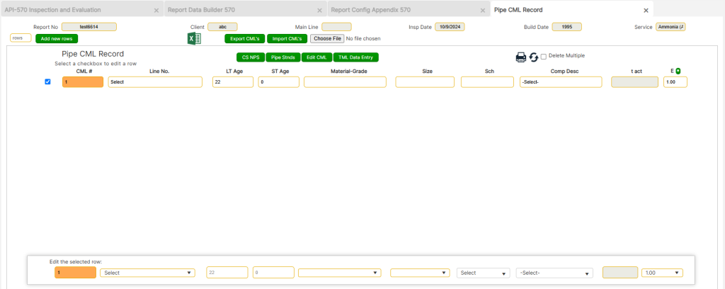
The Component Corrosion Monitoring Location (CML) Record section provides a structured interface for recording, managing, and analyzing thickness measurements for piping components. This section is essential for tracking corrosion rates, determining remaining life, and evaluating structural integrity based on API 570 requirements.
Accessing the Report Component CML Data Form
To access the Report Component CML Data Form from the home page:
- Choose [API 570 Pipe Insp].
- Click on the [Report Builder] button at the bottom of the page.
- Select Existing Report from the pull-down menu.
- Click on the [Report Appendix] button.
- Under Appendix A, select the [Pipe CML Record] button (page icon with a star in the middle).
Once inside the Pipe CML Record section, users can begin entering data into the designated cells within the Pipe CML Record data section.
- Entries should be made in the bottom table, ensuring that the CML number of interest is displayed before making new entries.
- The CML number will auto-populate, continuing from the last recorded CML entry.
Data Entry and Configuration
- Line Number: Represents the client line number found on P&ID diagrams. If P&IDs are unavailable, the user should enter a description that best identifies the line section. Using signifiers is recommended, e.g., a 3″ carbon steel caustic line on the first ISO drawing should be entered as:
- “3CS-CA-ISO1”
- Age: Entered as a numerical value, not a date (e.g., 9, 20, 34). Defaults to the tank age entered on the base page but can be manually changed if required.
- Material Grade: Select from the drop-down menu. If the required material is not listed, add it using the [Add New Materials] button at the top left of the page.
- Size & Schedule (Sch): Enter numerical values only (e.g., 2, 6, 8 instead of 2” or 6in).
- Component Description: Can be selected from the drop-down menu or entered manually.
- Joint Efficiency (E): Defaults to 1 but should be adjusted if the pipe is not seamless.
Pipe Standards & Nominal Pipe Size (NPS) Reference
- Use the [Pipe Stnds] and [CS NPS] buttons to determine:
- Standard pipe thicknesses
- Pipe schedules
CML Data Duplication and Editing
- Duplicating CML Entries:
- Users can duplicate CML entries after the first entry.
- Select the checkbox next to the CML of interest.
- Click the duplicate icon to create multiple CML points.
- Thickness Measurement Data (TML Data Entry):
- Click the [TML Data Entry] button to input thickness readings based on the unit designation selected on the base page.
- Each CML entry can include up to four thickness measurements (TML points).
- The final entry should be the lowest reading of that CML set, which will be used to calculate corrosion rates and remaining life.
- The CML descriptions appear at the top of the form, indicating the CML being edited.
Importing & Exporting CML Data
- Exporting Data
- Click on the [Export CML’s] button to export the dataset into an Excel spreadsheet.
- The exported spreadsheet can be populated using data from a log file (copy and paste into the spreadsheet).
- Importing Data
- Click the [Import CML’s] button.
- Select the [Choose File] button.
- Attach the spreadsheet file.
- Click [Import CML’s] to load data into the report.
- The CML will overwrite (replace) any CML with an identical number.
- The report number in the spreadsheet must match the target report number.
- Data Migration Between Reports
- Users can transfer datasets from one report to another by:
- Exporting the dataset,
- Modifying the report number,
- Re-importing the dataset into the new report.
- Users can transfer datasets from one report to another by:
Editing & Deleting CML Data
- Editing CML Data:
- Use the [Edit CML] button to modify existing entries.
- This option allows users to correct errors or refine thickness measurements.
- Deleting CML Entries:
- Single Line Deletion: Click the delete icon at the top right corner and confirm the deletion.
- Multiple Line Deletion:
- Click the delete multiple checkbox.
- Select multiple lines to delete.
- Click the delete icon and confirm.
Final Steps and Navigation
- Saving Progress: Always click the Save icon before navigating away to ensure data is not lost.
- Editing Options: Use the [Edit Component Data] or [Edit CML] buttons to modify values or delete erroneous entries.
- Printing: Click the print icon in the upper-right corner to print. Always save the report before previewing or printing.
- Navigation: Click the back arrow at the top-right corner to return to the Appendix page for the next step.
Report Pipe Calculations
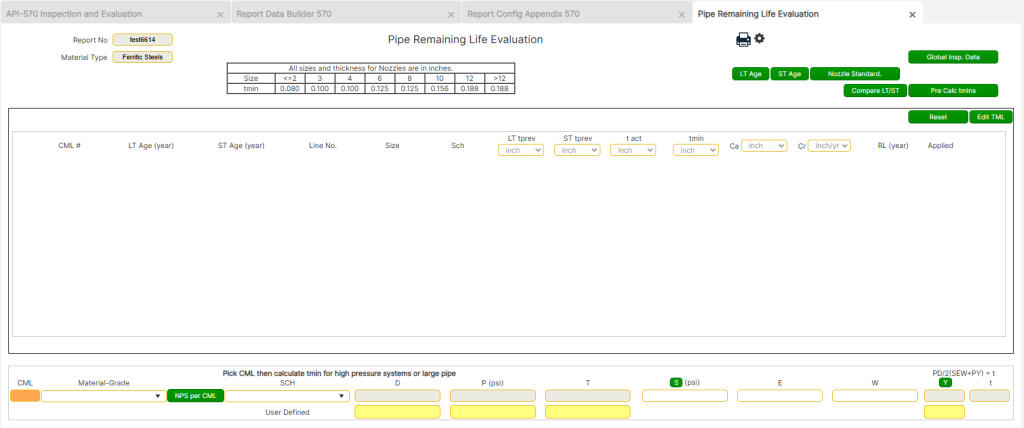
The Report Pipe Calculations section is designed to evaluate the remaining life of piping components by determining their minimum required thickness (tmin) and assessing their retirement criteria as per API-570 standards. This section provides a structured approach to corrosion rate analysis, thickness evaluations, and inspection planning, ensuring that piping systems meet safety and operational requirements. Users can override default values, access predefined industry standards, and perform additional calculations to support evaluation accuracy.
Accessing the Report Pipe Calculations Form
To access the Report Pipe Calculations Form from the home page:
- Choose [API 570 Pipe Insp].
- Click on the [Report Builder] button at the bottom of the page.
- Select Existing Report from the pull-down menu.
- Click on the [Report Appendix] button.
- Under Appendix B, select the [Remaining Life Calculations] button (page icon with a star in the middle).
This section provides pipe component evaluations based on previously entered data and the minimum required thickness values (tmins) as defined in API-570 standards.
Pipe Remaining Life Evaluations and Thickness Requirements
Retirement Thickness Determination (API-570 Section 7.3)
API-570 recommends that a pipe should have a greater thickness than the minimum calculated thickness (tmin) to account for:
- Undiscovered metal loss due to general and localized corrosion.
- Unanticipated loadings that may weaken the pipe structure.
- Resistance to normal loss over time.
This added safety margin is commonly referred to as “Practical Thickness.”
Each owner/user of a piping system must establish their own practical thickness values, which should be based on engineering evaluations specific to their operations.
Practical Thickness in API-570 Toolbox
The API-570 Toolbox provides pre-established practical thickness values, derived from:
- Industry-standard design parameters.
- Common inspection practices.
- Safety and operational considerations.
These values can be accessed by clicking on the [Pre Calc tmins] button in the upper right-hand corner of the calculation page. Additionally, the API-570 Reporting Module Base Page includes a custom table where users can input user-defined values to be used in the inspection report evaluations.
Editing Thickness Values
By default, the system automatically enters the following values:
- tprev (previous thickness measurement)
- tmin (minimum required thickness)
However, these values can be manually overridden:
- To change a thickness value: Simply type the new value in the source cell (on the base page or CML entry page).
- To apply the changes, click the [Reset] button to update the calculations.
- To edit CML data, use the [Edit TML] button. This allows you to:
- Delete incorrect entries.
- Enter alternate values with different decimal placements.
Nozzle and Pipe Support Data
Nozzle Standards
- The [Nozzle Standards] button provides a quick reference guide to all pipe/nozzle data.
- Click on [Nozzle Standards], then select the specific subject of interest to access detailed information.
Global Inspection Data
- The [Global Insp Data] button updates the next inspection intervals if:
- Any nozzle components appear to govern the inspection frequency.
- Users need a quick overview of basic inspection data.
Performing Additional Calculations
- The system allows users to select additional calculations to support the evaluation process.
- The default pressure and pipe support calculations apply to the main header, but users can choose whether to apply these calculations based on their specific needs.
Final Steps and Navigation
- Saving Progress: Always click the Save icon before navigating away to ensure data is not lost.
- Editing Options: Use the [Edit TML] or [Reset] buttons to modify values and update calculations.
- Printing: Click the print icon in the upper-right corner to print. Always save the report before previewing or printing.
- Navigation: Click the back arrow at the top-right corner to return to the Appendix page for the next step.
Report AutoCAD Pipe Iso Inspection Drawings
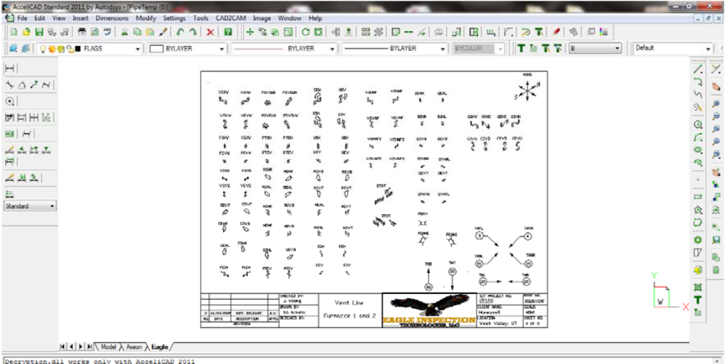
The Report AutoCAD Pipe Iso Inspection Drawings section enables users to generate and modify inspection drawings for piping systems using AutoCAD. These drawings play a critical role in documenting inspection results, identifying critical components, and ensuring compliance with API-570 standards. This section provides step-by-step instructions for accessing, editing, and saving AutoCAD drawings, ensuring that they accurately reflect the piping system under inspection.
Accessing the Report AutoCAD Inspection Drawings
To access the Report AutoCAD Pipe Iso Inspection Drawings, follow these steps:
- Navigate to the Appendix Page from the Report Builder.
- Click on the icon (page with the star) under Appendix C.
- Save the file to a project folder for reference and modifications.
- Print out the Ledger Drawing to use as a reference when constructing the shell drawing.
Before proceeding with modifications, ensure that:
- AutoCAD (Version 1997 or later) is installed.
- Field data sheets and drawings relevant to the project are available.
Editing and Modifying AutoCAD Pipe Iso Drawings
Once the CAD drawing is open and saved in a project folder, complete the following steps while referencing the field data sheets and drawings:
Editing Title Blocks and Drawing Text
- Open Paper Space (PS mode) by entering “PS” on the command line.
- Edit all title blocks and drawing text to include:
- Company Name
- Date of Inspection
- Other required text to comply with company drawing protocols.
Modifying the Pipe Iso Drawing in Model Space (MS mode)
- Enter “MS” in the command line to switch to Model Space.
- Insert the appropriate block of interest (e.g., VHSW) using the following command sequence:
- Command:
insert - Insertion Point: Pick the line where the block should be inserted.
- X Scale Factor: Enter default value.
- Y Scale Factor: Enter default value.
- Rotation Angle: Enter default value.
- Command:
Zoom to Limits- If the drawing does not fully appear, adjust the zoom scale to ensure full visibility.
- Command:
- Explode the Block and edit the drawing as necessary to reflect the design of the Pipe Iso system being inspected.
Final Steps and Navigation
- Saving Progress: Always click the Save icon before navigating away to ensure data is not lost.
- Editing Options: Use the [Edit Title Blocks] and [Modify Block] commands to adjust text and block components as needed.
- Printing: Click the print icon in the upper-right corner to print. Always save the drawing before previewing or printing.
- Navigation: Click the back arrow at the top-right corner to return to the Appendix page for the next step.
Report Checklists
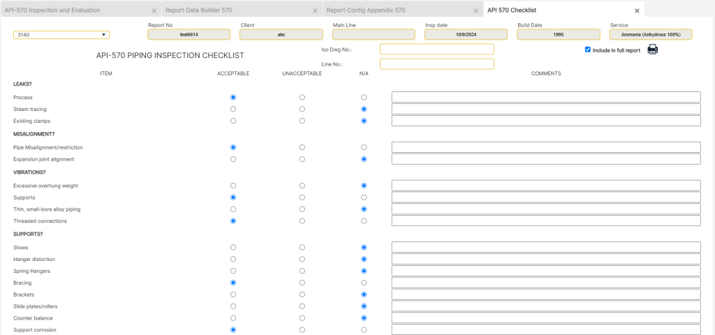
The Report Checklists section ensures that all required inspection items are verified and documented according to API-570 standards. This checklist serves as a structured quality control measure, allowing inspectors to systematically verify pipeline conditions, confirm regulatory compliance, and identify potential issues. The checklist is directly linked to inspection drawings (ISO-001) and must be carefully completed to ensure accurate reporting.
Accessing the Report Checklists
To access the Report Checklists, follow these steps:
- Navigate to the Report Builder from the home page by selecting [API 570 Pipe Insp].
- Click on the [Report Builder] button at the bottom of the page.
- Select Existing Report from the dropdown menu.
- Click on [Report Appendix], then select the [Checklist for ISO-001] button (page icon with a star) under Appendix D.
Once accessed, enter the following details:
- ISO Drawing Number – The identification number of the inspection drawing.
- Line Number – The piping system identification number associated with the inspection.
Completing the Report Checklist
- Scroll through the checklist and review each inspection item.
- Enter checks for relevant items that were verified during the inspection.
- Ensure that all mandatory checks are completed before saving the report.
Editing and Managing Checklist Records
- Modifying Entries: Checklist entries can be modified at any time by selecting the relevant section and making necessary updates.
- Deleting Entries:
- Click the delete icon at the top-right corner of the checklist.
- Confirm the deletion when prompted.
Final Steps and Navigation
- Saving Progress: Always click the Save icon before navigating away to ensure data is not lost.
- Editing Options: Use the checklist input fields to update or modify entries before finalizing the report.
- Printing: Click the print icon in the upper-right corner to print. Always save the report before previewing or printing.
- Navigation: Click the back arrow at the top-right corner to return to the Appendix page for the next step.
Report Inspection Photograph
The Report Inspection Photograph section allows inspectors to document visual evidence of pipeline conditions during an API-570 inspection. Properly captured inspection photographs help support findings, highlight areas of concern, and provide a visual record of the pipeline’s condition. These images can be included in the final inspection report by either uploading them directly or attaching a preformatted document.
Accessing the Report Inspection Photographs
To access the Report Inspection Photographs, follow these steps:
- Navigate to the Report Builder from the home page by selecting [API 570 Pipe Insp].
- Click on the [Report Builder] button at the bottom of the page.
- Select Existing Report from the dropdown menu.
- Click on [Report Appendix], then select the [Upload Files] button under Appendix E.
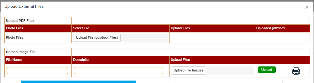
Uploading Inspection Photographs
Option 1: Uploading a Preformatted PDF File
Users who prefer to format photographs in a Word document before submission should follow these steps:
- Prepare the document in Microsoft Word, ensuring all photos are properly labeled and formatted.
- Save the document as a PDF.
- In the Report Inspection Photographs section, click [Choose File].
- Locate and select the PDF file to be uploaded.
- Click [Upload] to attach the document to the inspection report.
Option 2: Uploading Photographs Directly
If uploading photographs individually, complete the following steps:
- Enter a Caption – Provide a brief description in the header space for each photo.
- Click [Choose File] and select the image to be uploaded.
- Click [Upload] to add the selected image to the report.
- Repeat steps 1-3 until all required photographs are uploaded.
Final Steps and Navigation
- Saving Progress: Always click the Save icon before navigating away to ensure data is not lost.
- Editing Options: Use the caption text field to update descriptions before finalizing the report.
- Printing: Click the print icon in the upper-right corner to print. Always save the report before previewing or printing.
- Navigation: Click the back arrow at the top-right corner to return to the Appendix page for the next step.
All other Appendices
The remaining Appendices in the API-570 Inspection Report serve as supplementary documentation sections that allow inspectors to attach relevant files, reference materials, and additional reports. These appendices provide supporting evidence, calculations, or any other pertinent data that need to be included in the final inspection report.
Accessing the Remaining Appendices
To access any of the remaining Appendices, follow these steps:
- Navigate to the Report Builder from the home page by selecting [API 570 Pipe Insp].
- Click on the [Report Builder] button at the bottom of the page.
- Select Existing Report from the dropdown menu.
- Click on [Report Appendix], then select the Appendix of interest from the list.
- Click the [Upload Files] button under the selected Appendix.
Uploading Files to Appendices
Once inside the selected Appendix page, complete the following steps to attach necessary files:
- Click the [Choose File] button.
- Navigate to the file location and select the PDF file to be uploaded.
- Click [Upload] to add the file to the report.
- Repeat steps 1-3 until all required attachments are uploaded.
Final Steps and Navigation
- Saving Progress: Always click the Save icon before navigating away to ensure data is not lost.
- Editing Options: Ensure that all uploaded files are correct and relevant before finalizing the report.
- Printing: Click the print icon in the upper-right corner to print. Always save the report before previewing or printing.
- Navigation: Click the back arrow at the top-right corner to return to the Appendix page for the next step.
Report Write-up and Recommendations
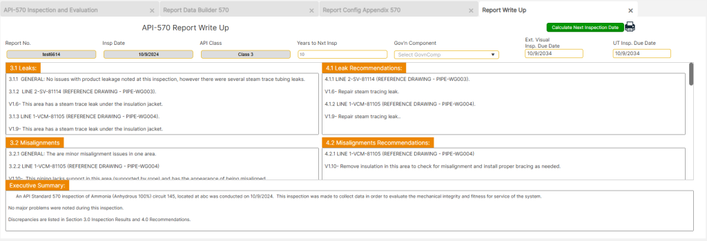
The Write-up and Recommendations section serves as the final documentation area where inspection findings, calculation results, and recommendations are formally recorded. This section includes editable text fields for documenting key observations, specifying next inspection intervals, and summarizing critical findings in the Executive Summary (ES).
Accessing the Write-up and Recommendations Page
To access the Write-up and Recommendations page, follow these steps:
- From the Base Page, navigate to the [Write-up and Recommendations] section.
- This section is divided into multiple windows for entering findings and recommendations based on component evaluations.
Editing Write-up and Recommendations
Report Findings and Recommendations
- Default Text: Each section comes pre-filled with a default text that needs to be edited based on the inspection findings.
- Customization: The user can edit, delete, or replace the default text as needed to reflect the actual inspection results.
- Component-Based Reporting: Recommendations should be specific to each component and include necessary actionable steps to address identified issues.
Inspection Intervals and Governing Component
- The “Years to Next Insp.” field defines the time frame for the next ultrasonic thickness (UT) inspection and is typically set to 5 years for corrosion rate evaluations.
- The governing component is usually the component with the shortest remaining life, and the next inspection date is calculated accordingly.
Executive Summary (ES) and Key Findings
- Default Text: The Executive Summary (ES) also includes pre-filled text, which must be reviewed and customized based on actual findings.
- Significant Findings Only:
- The ES should only contain major issues, particularly those with high cost implications or those that limit operational parameters of the tank or piping system.
- Findings that need to be included in the Executive Summary should first be documented in the body of the report and then copied into the ES with necessary modifications for clarity.
Final Steps and Navigation
- Saving Progress: Always click the Save icon before navigating away to ensure that data is not lost.
- Editing Options: Modify default text in the Write-up and Recommendations section to reflect accurate inspection results.
- Spell Check: Place the cursor in the Write-up or Executive Summary text fields, then press F7 to run a spell check.
- Printing: Click the print icon in the upper-right corner to print. Always save the report before previewing or printing.
- Navigation: Click the back arrow at the top-right corner to return to the Appendix page for the next step.