
Introduction
The API modules 653, 510, and 570 are central to ensuring that storage tanks, pressure vessels, and piping systems meet the stringent requirements set forth by the American Petroleum Institute (API). Managing these inspections effectively, especially in remote or challenging locations, requires robust tools designed for the job. Enter the API Collector, an innovative app designed specifically to support field operations in the oil and gas sector.
The API Collector is a purpose-built application available on tablets, tailored to streamline the data collection process during inspections governed by API 653, 510, and 570. One of its standout features is its ability to function offline, making it an invaluable tool for inspectors working in the field, where internet connectivity can be unreliable or entirely absent. This offline capability ensures that inspection data is captured accurately and consistently, regardless of the location, and can be synchronized with the central system once a connection is restored.
Designed with the specific needs of field inspectors in mind, the API Collector offers a comprehensive suite of tools to facilitate the inspection process. It allows users to collect detailed data, including images, notes, and other records, directly on-site. This data can then be seamlessly uploaded to the HUB, the centralized repository where all inspection information is stored and managed. The ability to upload images is particularly beneficial, as it provides visual documentation of the condition of assets, aiding in the accurate assessment and decision-making process.
Demo
The API Collector’s intuitive interface is optimized for tablet use, ensuring that inspectors can easily navigate the app while on the job. Whether it’s filling out inspection forms, recording measurements, or attaching photographic evidence, the app simplifies these tasks, reducing the time spent on data entry and minimizing the potential for errors. The the ability to work offline means that inspectors are not limited by the availability of a network connection, allowing them to focus entirely on the inspection process without interruption.
How-to-Guide
Getting Started
To start using the API Collector, follow these steps:
Installation & Setup
- Download the App: The API Collector is available for tablets running Windows or Android.
- Login & Authentication: Enter your credentials to access inspection reports and stored data.
- Select Inspection Type: Choose between API 653, 510, or 570 based on the equipment being inspected.
Logging In
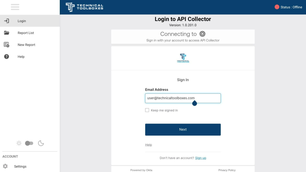
Online Mode
- Once the application is launched, users can log in using the same credentials as the Pipeline Toolbox HUB.
- The system will authenticate user access and ensure that only authorized personnel can use the API Collector.
- The license verification process can be completed with the support engineer if needed.
Offline Mode
- Users can utilize the application without logging in, but access is restricted to visualizing and creating reports.
- The API Collector supports offline data collection, ensuring that inspections can continue uninterrupted in areas with poor or no connectivity.
- Data is stored locally and will automatically synchronize with the HUB once an internet connection is available.
Home Page
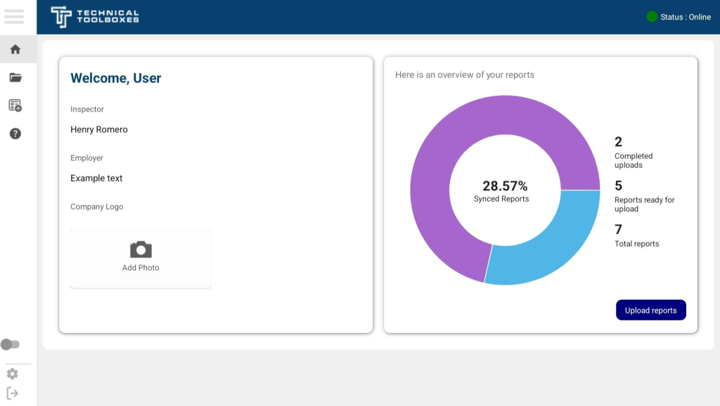
User Profile Section
- Displays the inspector’s name and employer information.
- Users can upload a company logo by clicking on the “Add Photo” button.
- Ensures that all reports are correctly attributed to the respective inspector.
Report Status Overview
- Provides a visual breakdown of reports in progress, completed, or pending upload.
- A circular progress chart displays the percentage of synced reports for quick reference.
- Breakdown of report status includes:
- Completed Uploads: The number of reports successfully uploaded to the HUB.
- Reports Ready for Upload: Reports that have been finalized but not yet synced.
- Total Reports: The total count of all reports stored within the API Collector.
Status Indicator
- The top right of the screen displays the current connectivity status:
- Green Dot (Online): Indicates an active internet connection for syncing reports.
- Gray or Red Dot (Offline): Denotes offline mode, meaning reports will be stored locally until the connection is restored.
Upload Reports Button
- Allows users to manually sync completed reports with the HUB when an internet connection is available.
- Ensures that all finalized reports are properly stored and backed up in the system.
Uploading & Syncing Reports
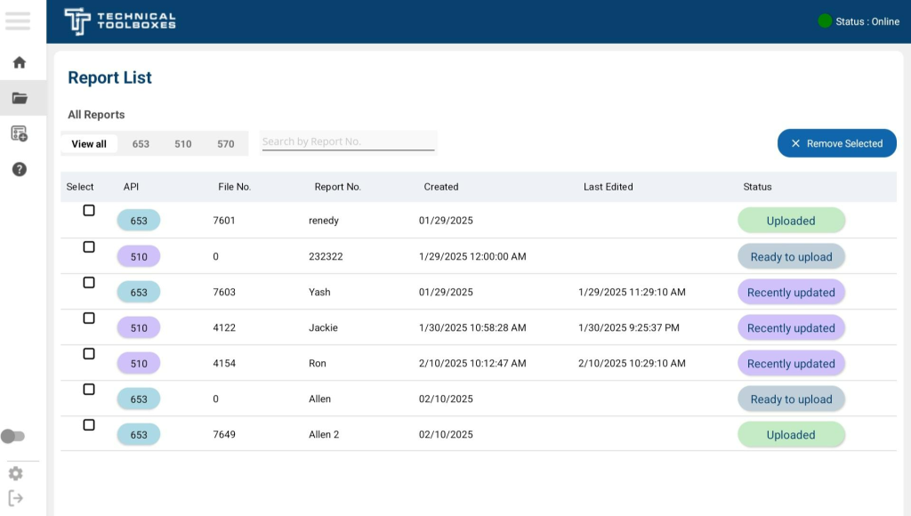
Report List Overview
- The Report List provides a comprehensive view of all reports created within the API Collector, categorized by API standard: 653, 510, and 570.
- Users can filter reports using the search bar or by selecting a specific API type.
- The status column indicates whether a report has been recently updated, is ready for upload, or has already been uploaded.
Uploading Reports to the HUB
- Once internet access is available, users can upload reports to the HUB directly from the Report List page.
- Uploaded reports undergo review and compliance checks to ensure accuracy before being finalized.
- Reports can also be uploaded during the report building process within individual API modules.
Report Status Indicators
- Uploaded: The report has been successfully synced to the HUB.
- Ready to Upload: The report is complete and awaiting upload.
- Recently Updated: The report has been modified but not yet uploaded.
Bulk Upload and Management
- Users can select multiple reports and remove them or upload them in batches for efficiency.
- The Remove Selected button enables users to delete unnecessary reports.
Syncing Data Across Devices
- If the user has been working offline, all collected data will be stored locally until an internet connection is restored.Upon reconnection, reports can be synchronized with the HUB, ensuring no data is lost.
Select Report type
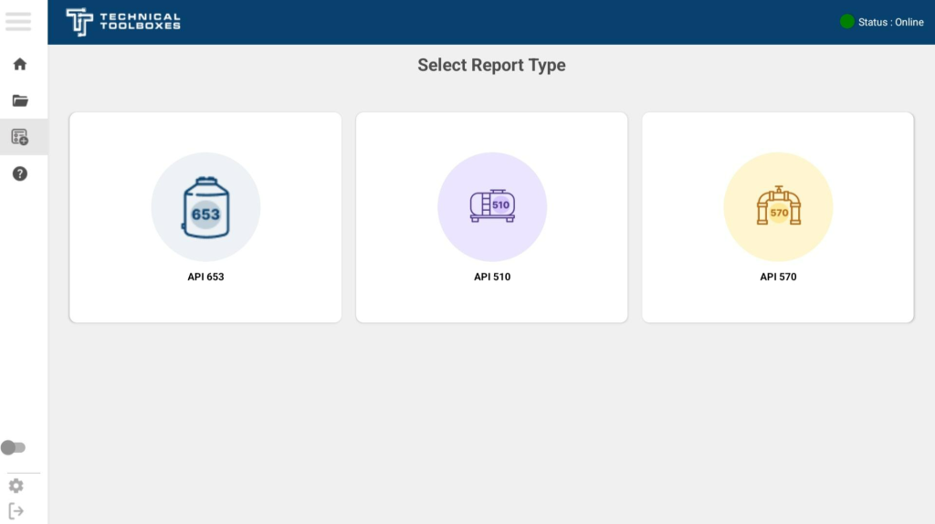
The “New Report” tab initiates the inspection process for three key API standards: API 653, API 510, and API 570. This section enables inspectors to select the appropriate report type based on the specific asset being evaluated, ensuring compliance with the relevant industry standards.
API Report Types
- API 653 – Storage Tanks
- Designed for aboveground storage tank inspections.
- Ensures compliance with API 653 standards, covering corrosion assessments, structural integrity, and repairs.
- Used for inspections related to tank bottom thickness, settlement evaluation, and shell conditions.
- API 510 – Pressure Vessels
- Used for pressure vessel inspections, ensuring compliance with API 510 standards.
- Covers wall thickness assessments, weld integrity, and fitness-for-service evaluations.
- Focuses on vessels subject to internal pressure, external loads, and operational stress.
- API 570 – Piping Systems
- Developed for piping system inspections in compliance with API 570 regulations.
- Evaluates corrosion rates, remaining life, and structural integrity of process piping.
- Essential for maintaining safe and efficient pipeline operations.
API 653
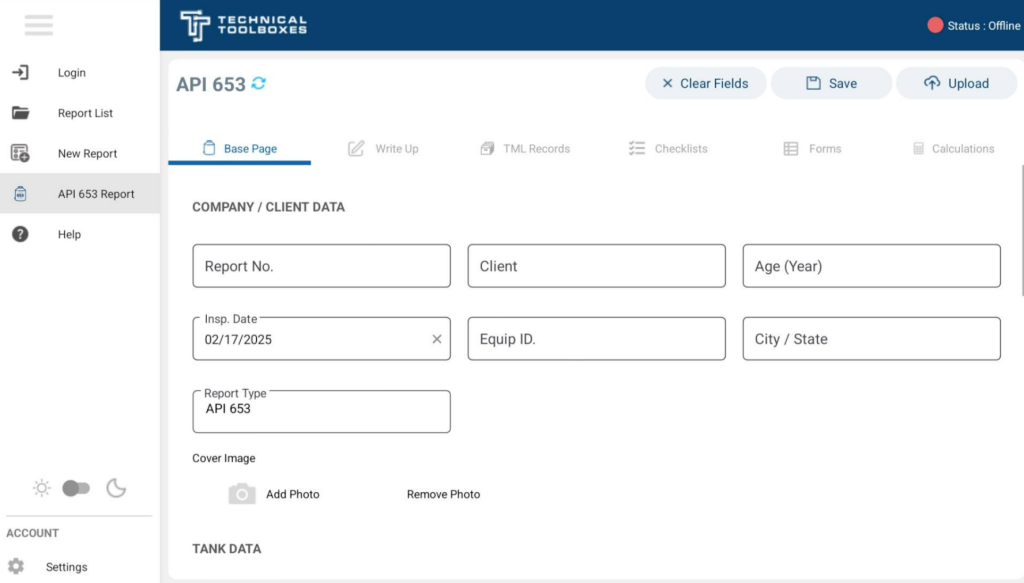
Base Page Section
The Base Page is the foundational step in the API 653 report-building process. This section allows inspectors to input critical company, client, and asset data related to storage tank inspections. The base page ensures that essential details are captured accurately, forming the backbone of the entire report.
The Base Page consists of three primary sections:
- Company / Client Data
- Tank Data
- Thickness Readings & Additional Information
Each section plays a crucial role in structuring the inspection report and ensuring that all necessary details are recorded efficiently.
Company / Client Data
This section contains the fundamental identification details of the inspection, including:
- Report Number – A unique identifier assigned to each inspection report.
- Client Name – The company or entity requesting the inspection.
- Age (Year) – The number of years since the tank was first put into service.
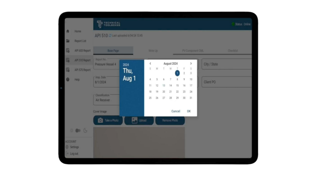
- Inspection Date – The date of the current inspection.
- Equipment ID – A unique identifier or serial number assigned to the specific tank.
- City / State – The location where the inspection is being conducted.
- Report Type – This field automatically populates as API 653, indicating the type of inspection being performed.
- Cover Image – Inspectors can add or remove a photo for better identification and reference.
This section ensures that every API 653 report is correctly labeled and associated with the right client and equipment, streamlining documentation and future reference.
Tank Data
The Tank Data section captures comprehensive details about the storage tank being inspected. These details are essential for evaluating compliance with API 653 standards.
Key fields include:
- Capacity Type & Capacity – Specifies the unit (e.g., gallons) and the maximum volume the tank can hold.
- Service – Describes the type of fluid or product stored in the tank.
- Construction Code – Identifies the construction standard used, commonly API 650 for aboveground storage tanks.
- Shell Construction – Indicates how the shell is built, such as butt-welded.
- Foundation – Specifies the type of foundation, e.g., concrete, that the tank is supported on.
- Roof Type – Describes the tank roof structure, such as Fixed/Cone.
- Operating & Local Mean Temperatures – Captures both the operating and local environmental temperatures in degrees Fahrenheit (°F).
- Design Temperature – The maximum temperature the tank was designed to withstand safely.
- Plate Specification – Defines the material specification for the tank’s plates, such as A 283M C.
- Nominal Diameter / Width – The diameter of the tank in feet.
- Height / Length – The overall height of the tank.
- Safe Fill Height – The maximum level to which the tank can be safely filled without risk of overflow.
- Corrosion Allowance (inch) – The additional material thickness included in the design to compensate for future corrosion loss.
- Joint Efficiency (E) – Represents the efficiency factor of welded joints based on construction year and type of joint used.
- Manufacturer – Identifies the tank’s manufacturer.
- Specific Gravity (SG) – Defines the density of the stored liquid relative to water (e.g., 0.79 – Acetone).
- Insulation Type – Specifies if insulation is used, such as None or other materials.
- NDE Methods – Lists the Non-Destructive Examination (NDE) techniques used for inspection.
- Year Built – Records the year the tank was originally constructed.
- Type of Inspection (In-Service/Out-of-Service) – Specifies whether the inspection is being performed while the tank is in operation or offline.
This section ensures that all relevant physical and structural details of the tank are properly documented, forming the basis for further inspection calculations.
Thickness Readings
The thickness readings section allows inspectors to record measured thickness values at multiple points on the tank structure, including:
- Crs 1 to Crs 8 – Corrosion readings taken at different critical points around the tank.
- Roof / End 1 & Floor / End 2 – Thickness readings specifically for the tank roof and floor components.
User Actions and Navigation
- Save Data: Always click the “Save” button before navigating away to ensure that all entered information is stored securely.
- Clear Fields: The “Clear Fields” button allows users to reset the form and remove all entered data if needed.
- Upload to HUB: Once the base page is completed, users can click “Upload” to sync the report to the HUB when an internet connection is available.
- Navigation Shortcuts: The top navigation bar provides direct access to other sections, including Write-Up, TML Records, Checklists, Forms, and Calculations.
Write-Up Section
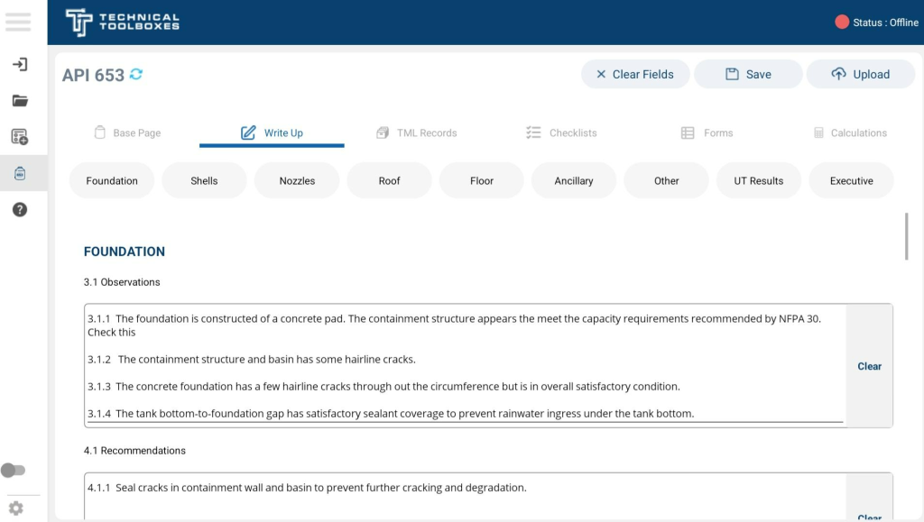
The Write-Up section is a crucial part of the API 653 report, allowing inspectors to record detailed observations and recommendations for various storage tank components. This section is designed to provide structured and comprehensive reporting while improving efficiency through voice-to-text functionality, unlimited image capture, and offline capabilities.
The Write-Up section is divided into multiple component-specific categories, making it easy for inspectors to input data for specific areas of the tank system. The available sections include:
- Foundation
- Shells
- Nozzles
- Roof
- Floor
- Ancillary Components
- Other Findings
- Ultrasonic Testing (UT) Results
- Executive Summary
Quick Navigation Using Top Icons
At the top of the Write-Up section, there are shortcut icons representing each category. Clicking on any icon allows the user to jump directly to that specific section without having to scroll through the entire form. This feature improves efficiency and streamlines the inspection process.
Key Features of the Write-Up Section
Unlimited Image Capture & Annotation
To enhance documentation, the Write-Up section supports unlimited image uploads for each component.
- Image Sources: Inspectors can either select images from the gallery or capture photos instantly using the tablet’s camera.
- Customization: Each image can be renamed and provided with a detailed description to clarify its significance.
- Unlimited Uploads: There is no restriction on the number of images that can be added per section, ensuring thorough visual documentation.
Voice-to-Text Feature
For faster and more efficient documentation, the Write-Up section supports voice-to-text functionality.
- Works Online and Offline: Voice input can be used even in remote locations where internet access is unavailable.
- Reduces Manual Data Entry: Instead of typing, inspectors can dictate observations and recommendations, significantly speeding up the process.
Observations & Recommendations Fields
Each section is structured to include default text:
- Observations (3.x Series) – Detailed findings on the condition of the tank components.
- Recommendations (4.x Series) – Suggested corrective actions based on the observations.
Each section features a dedicated clear icon that allows users to instantly remove all default text, providing a clean slate for customized input.
User Actions and Navigation
- Save Data: Click the “Save” button to store all observations, recommendations, and edits before exiting the Write-Up section.
- Clear Default Text: Each section has a “Clear” icon, allowing users to remove default text and input custom observations.
- Voice-to-Text Feature: Users can dictate their findings instead of typing, improving efficiency in both online and offline modes.
- Image Capture & Upload: Each section allows for unlimited image attachments, either captured instantly or selected from the gallery. Users can rename and add descriptions to each image.
- Navigation Shortcuts: The tabbed sections at the top enable quick movement between Foundation, Shells, Nozzles, Roof, Floor, Ancillary, Other, UT Results, and Executive Summary.
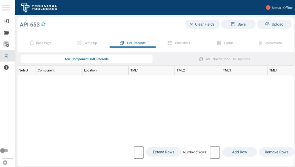
TML Records Section
The TML (Thickness Measurement Location) Records section in the API 653 Report provides a structured format for recording thickness measurements of components and nozzles. This section is crucial for tracking corrosion rates and determining remaining life assessments based on past and current readings.
The TML Records interface is divided into two primary categories:
- AST Component TML Records: For tracking thickness data on storage tank components.
- AST Nozzle/Pipe TML Records: For recording thickness values specific to nozzles and pipe connections.
AST Component TML Records
This table allows users to input and monitor thickness measurements for tank components. Each row represents a different component, and multiple columns capture different thickness measurements at various points.
Key Features:
- Component Identification: Users can specify which tank component is being measured.
- TML Location: Indicates where the thickness reading is taken.
- Multiple Thickness Data Entries: Up to six different thickness readings (TML1–TML6) can be recorded per component.
- Customizable Row Entry: Users can add or remove rows dynamically based on the number of TML locations required.
- Expand Rows Feature: A user-defined number of rows can be added simultaneously for batch data entry.
Adding and Managing Rows:
- “Add Row”: Inserts a new row to enter additional TML readings.
- “Remove Rows”: Deletes selected rows.
- “Extend Rows”: Allows bulk row creation for rapid data entry.
AST Nozzle/Pipe TML Records
This section is dedicated to recording thickness measurements specifically for nozzles and pipe connections, which are critical points of potential degradation.
Key Features:
- Photo Capture Integration: Each TML entry allows users to attach a reference image for documentation purposes. Images can be captured instantly using the device camera or selected from the gallery.
- Component ID and Service Entry: Users can label the nozzle or pipe section with an identifier and note its specific service condition.
- Multi-Point Thickness Tracking: Allows for up to four thickness readings per nozzle location (Q1t–Q4t).
- Previous Thickness & Minimum Thickness Tracking: Includes fields for Tprev (previous thickness reading), minimum allowable thickness, and component age.
- Customizable Rows: Similar to component records, users can dynamically add or remove nozzle thickness data entries.
User Actions and Navigation
- Save Data: Click the “Save” button to ensure recorded measurements are stored before leaving the page.
- Clear Fields: The “Clear Fields” button allows users to reset the form and remove any entered data.
- Upload to HUB: Once all data is collected, users can sync the report to the HUB for cloud storage and further analysis.
- Navigation Shortcuts: The TML Records tab is accessible from any other section of the report via the top navigation bar.
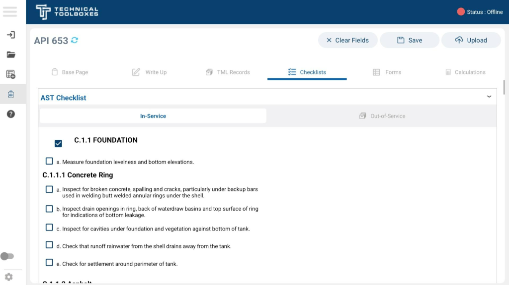
Checklists Section
The Checklists section in the API 653 module is designed to ensure thorough documentation of inspection points,
The Checklists section in the API 653 module ensures a comprehensive inspection process for Aboveground Storage Tanks (ASTs). It consists of three distinct checklists, each designed to address different inspection scenarios. Inspectors can systematically verify tank integrity, regulatory compliance, and maintenance needs by marking off key inspection points.
There are three primary types of checklists available:
- AST Checklist – In-Service: Used for tanks that remain in operation during the inspection, focusing on active corrosion monitoring, structural integrity, and regulatory compliance.
- AST Checklist – Out-of-Service: Applied when a tank is temporarily offline for maintenance or a detailed evaluation, allowing for internal inspections.
- Steel Tank Institute AST Inspection: Covers industry-specific best practices and compliance guidelines based on Steel Tank Institute (STI) standards.
Inspectors can toggle between In-Service and Out-of-Service checklists using the selection bar at the top. The system ensures that all critical aspects of the tank’s condition are reviewed before finalizing the report.
Navigation and Saving
- Saving Progress: Click the Save button to retain entered data before switching sections.
- Clearing Fields: Click Clear Fields to reset checklist inputs.
- Uploading the Checklist: Click Upload to sync the completed checklist with the HUB.
- Returning to Other Report Sections: Navigate to other sections (Base Page, Write-Up, TML Records) using the top navigation tabs.
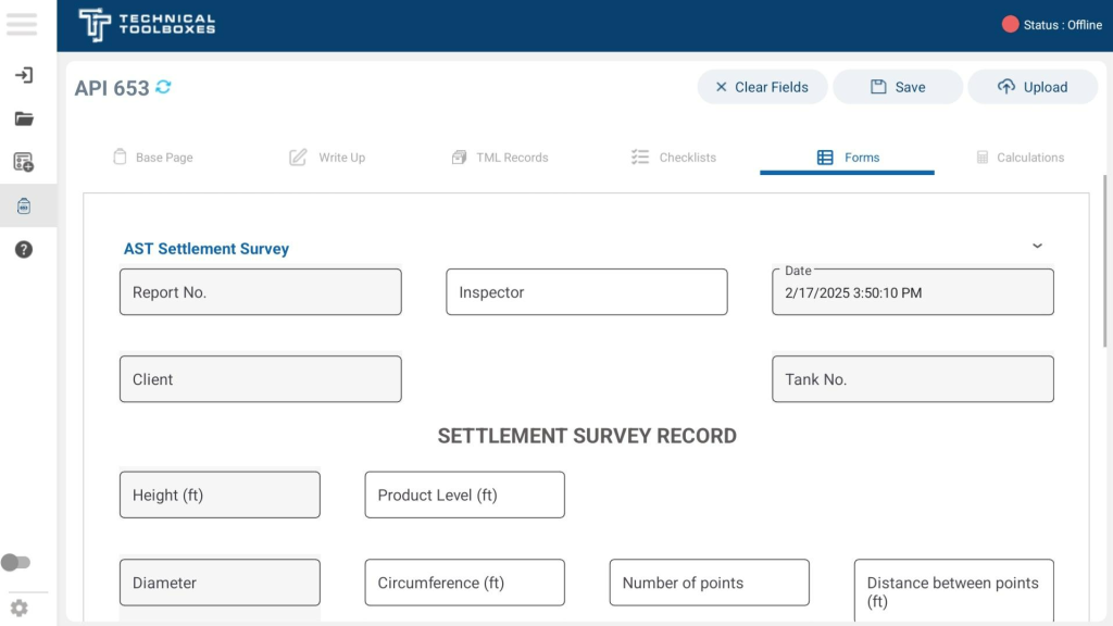
Forms Section – Settlement Survey Form
The Forms section in the API 653 report module currently includes the AST Settlement Survey Form, which is used to document tank settlement data. This form enables inspectors to record precise measurements regarding the structural integrity of the tank foundation, helping assess any shifts or deformations over time.
Settlement Survey Record Fields
The Settlement Survey Form consists of various fields designed to capture detailed measurements of the tank and its surrounding foundation:
- General Information
- Report No. – Unique identifier for the report.
- Inspector – Name of the inspector conducting the survey.
- Date – The date and time of the survey.
- Client – Name of the client or company commissioning the inspection.
- Tank No. – Identifier for the specific tank being inspected.
- Measurement Parameters
- Height (ft) – The total height of the tank.
- Product Level (ft) – The level of the product inside the tank at the time of measurement.
- Diameter (ft) – The measured diameter of the tank.
- Circumference (ft) – The calculated circumference based on the diameter.
- Number of Points – The number of measurement points taken around the tank.
- Distance Between Points (ft) – The spacing between settlement measurement points.
Types of Transit Measurements
The Settlement Survey Form allows inspectors to select the method of transit measurement used for recording settlement data:
- Conventional Transit – Manual leveling using traditional surveying equipment.
- Laser Transit (Manual Leveling) – A manual laser transit setup that requires the operator to adjust readings manually.
- Laser Transit (Automatic Leveling) – An advanced laser transit that automatically levels and records readings.
Survey Guidelines
The system includes built-in survey guidelines to assist inspectors in ensuring accuracy and consistency in measurements:
- Point #1 must be located at the center of the highest point along the tank circumference at the base weld of the first course.
- Survey points should be calculated to even numbers to best fit the cosine curve.
- Distance between points is limited to a maximum of 31.42 feet.
- All quadrants of the tank must be included in the measurement process to ensure comprehensive settlement assessment.
Recording Settlement Data
Once the inspector has set up the survey points, the Settlement Survey Record Table enables entry of multiple data points. This table includes:
- Points – The number assigned to each measurement location.
- Stn 1 – Stn 6 – Readings taken at different measurement stations.
- Readings in: – Allows inspectors to specify the unit of measurement (e.g., feet, inches).
Additional rows can be added or removed as necessary to accommodate more data points.
User Actions and Navigation
- Saving Progress: Click the Save button to store entered data before navigating away.
- Clearing Fields: The Clear Fields button resets all input fields for a fresh entry.
- Uploading Data: Once measurements are finalized, click Upload to sync data with the HUB.
- Adding Rows: Users can dynamically expand the form by clicking Add Row to accommodate additional survey points.
- Navigation: Click on the back arrow at the top-left corner to return to the previous page.
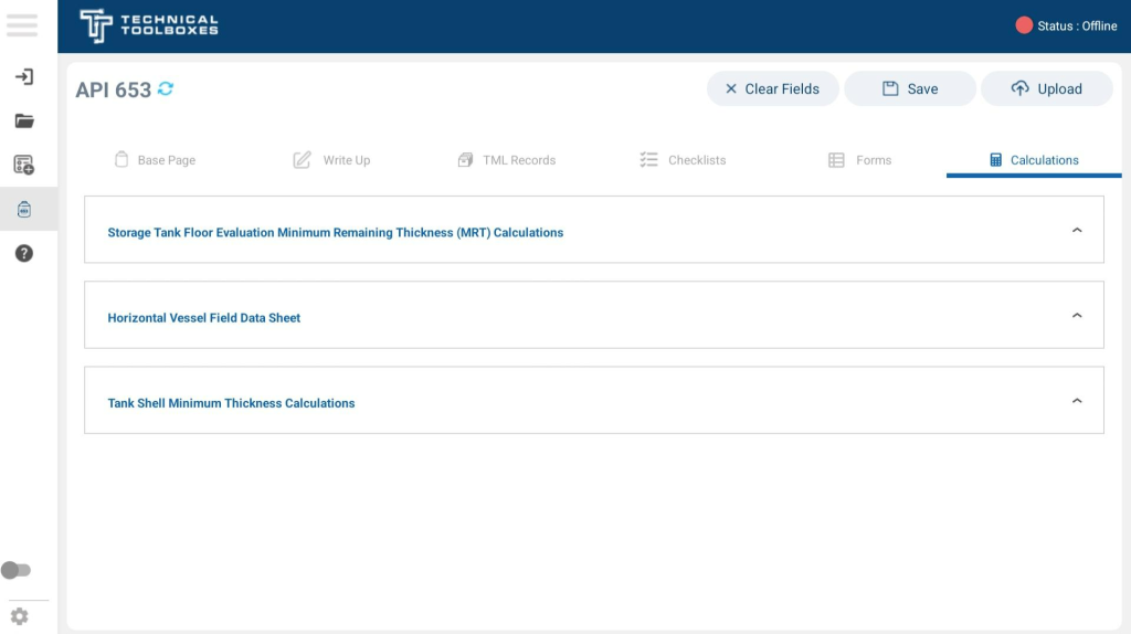
Calculations Section
The Calculations section within the API 653 report module is designed to assist inspectors in performing critical calculations related to tank integrity, thickness evaluations, and structural assessments. This section includes automated formulas that use inputted data from other report sections to generate precise calculations, ensuring compliance with API 653 standards.
To access the Calculations tab, navigate to the API 653 report module and select the Calculations section. This area provides three primary calculation tools, each of which expands upon selection:
- Storage Tank Floor Evaluation – Minimum Remaining Thickness (MRT) Calculations
- Horizontal Vessel Field Data Sheet
- Tank Shell Minimum Thickness Calculations
Each of these tools aids in evaluating key tank parameters to ensure structural reliability and regulatory compliance.
Storage Tank Floor Evaluation – Minimum Remaining Thickness (MRT) Calculations
This tool calculates the minimum remaining thickness of the tank floor based on input thickness measurements, corrosion rates, and previous inspections. The goal is to determine whether the floor can remain in service or if repairs/replacements are required.
- Inputs Required:
- Thickness readings from multiple points on the tank floor.
- Corrosion rates from previous inspections.
- Inspection history and remaining life estimation.
- Output Generated:
- Computed MRT values indicating whether the floor meets minimum thickness requirements.
- Recommendations for continued use, repair, or replacement based on API 653 standards.
Horizontal Vessel Field Data Sheet
This tool helps inspectors document and calculate key data points for horizontal storage vessels, including:
- Tank dimensions
- Thickness measurements
- Operating pressure and temperature
These calculations help inspectors assess vessel safety, ensure compliance, and determine if structural reinforcements are required.
Tank Shell Minimum Thickness Calculations
The Tank Shell Minimum Thickness Calculation tool assesses the integrity of the tank shell by determining:
- The minimum required thickness based on service conditions and applied stress.
- Corrosion rates and expected lifespan before maintenance is required.
- Inputs Required:
- Shell thickness readings from various elevations.
- Design pressure and temperature.
- Corrosion allowance and past inspection data.
- Output Generated:
- Minimum allowable thickness based on API 653 formulas.
- Predicted remaining service life.
User Actions and Navigation
- Performing Calculations: Users can enter or update relevant data, and the system will auto-calculate based on API formulas.
- Saving Progress: Always click the Save button to store calculation results.
- Clearing Fields: The Clear Fields button resets any entered values for fresh input.
- Uploading Results: Once calculations are finalized, click Upload to sync data with the HUB.
- Navigation: Click the back arrow at the top-left to return to the report section or access other calculations.
Finalizing and Uploading
Once all required data has been entered and calculations have been completed, the final step is to save and upload the report to the HUB. This process ensures that inspection results are securely stored, accessible for review, and available for compliance checks.
Saving Your Report
Before uploading, users should save their report to prevent any data loss. Click on the Save button located at the top-right corner of the screen to ensure all entered values, images, and calculations are stored.
- Tip: If the device is offline, the report will be saved locally and can be uploaded once an internet connection is restored.
Uploading to the HUB
After saving the report, users can proceed with uploading the final version to the HUB.
- Log in to the application if not already signed in.
- Click on the Upload button at the top-right of the screen.
- A confirmation pop-up will appear, displaying a unique ID number attached to the report. This serves as a reference for tracking and retrieval.
- The system will automatically sync the uploaded report with the HUB, making it available for review.
Verifying Report Status in the Report List Tab
After uploading, navigate to the Report List tab to confirm that the report has been successfully submitted.
- The report status will be updated to reflect its current state (e.g., Uploaded, Pending Review, or Approved).
- Users can search for the report using the ID number generated during the upload process.
This finalization step ensures that all API 653 inspection reports are accurate, properly stored, and ready for compliance verification.
API 510
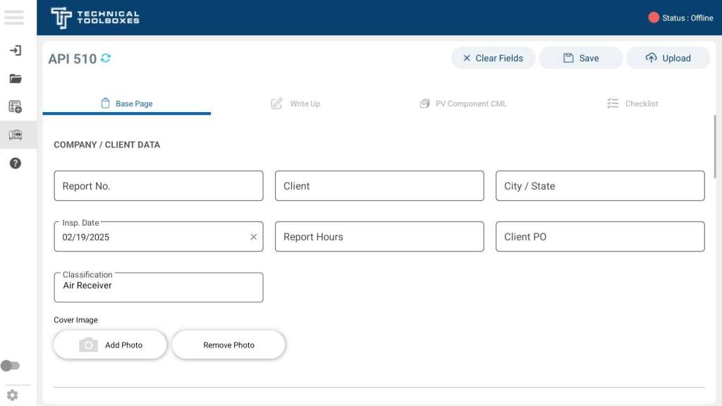
Base Page Section
The Base Page of the API 510 report serves as the initial data entry point for pressure vessel inspections. It captures critical details about the inspection, including company and client information, vessel classification, and key specifications required for compliance with API 510 standards.
Company / Client Data
- Report No. – Unique identifier assigned to the report.
- Client – Name of the company or client requesting the inspection.
- City / State – Location details of the inspection site.
- Inspection Date – Date when the inspection was conducted.
- Report Hours – Total hours recorded for the inspection.
- Client PO – Purchase order reference for the inspection services.
- Classification – Specifies the type of pressure vessel, such as Air Receiver.
Vessel Specifications
- Report Type – Defines the type of report being generated (e.g., Simple PV).
- Inspection Type – Indicates whether the vessel is In-Service or Out-of-Service.
- Vessel Configuration – Specifies the structure type (e.g., Vertical or Horizontal).
- Vessel ID – Identification number of the pressure vessel.
- Location – Physical site where the vessel is situated.
- Year Built – The construction year of the vessel.
- Inside Diameter (in) – The internal diameter measurement of the vessel.
- Length / Height (in) – Dimensions of the vessel.
- Construction Code – Reference to applicable design codes (e.g., API 620).
- Material Type – Specifies the material used for the vessel (e.g., Carbon Steel).
- NB No. – National Board number assigned to the vessel.
- Product – The type of substance or fluid the vessel contains.
- Maximum Allowable Working Pressure (MAWP) (psi) – Defines the vessel’s pressure limit.
- Minimum Design Metal Temperature (MDMT) (°F) – The lowest temperature at which the vessel material can function safely.
Operational and Structural Details
- Operating Pressure (psi) – The pressure at which the vessel typically operates.
- Design Temperature (°F) – Maximum temperature for which the vessel was designed.
- Operating Temperature (°F) – The usual temperature during normal operation.
- Insulation Type – Specifies if the vessel is insulated (e.g., None).
- Insulation Thickness (in) – If applicable, the thickness of the insulation.
- Header Type (General) – Specifies the type of header (e.g., 2:1 Ellipsoidal).
Component Data
The Base Page also includes sections for individual Component Data, where inspectors can specify various parts of the vessel such as:
- Component ID – Unique identifier for each part of the vessel.
- Component Description – Defines the type of component (e.g., Boot Head, Shell).
- Head Type – Specifies the shape of the vessel head (e.g., Conical).
- Nominal Thickness (in) – The measured thickness of the component.
User Actions & Navigation
User Actions
- Enter Data – Users can fill out each section with inspection details.
- Add Photo – Upload a cover image of the vessel.
- Remove Photo – Delete the uploaded image if necessary.
- Clear Fields – Resets all input fields to default.
- Save – Saves the entered information for later editing.
- Upload – Submits the report to the HUB for final processing.
Navigation
- The Base Page serves as the starting point of the API 510 inspection process.
- Users can navigate to the next section (Write-Up) using the top navigation bar.
- The Base Page ensures that all fundamental vessel details are captured before proceeding to more detailed inspections.
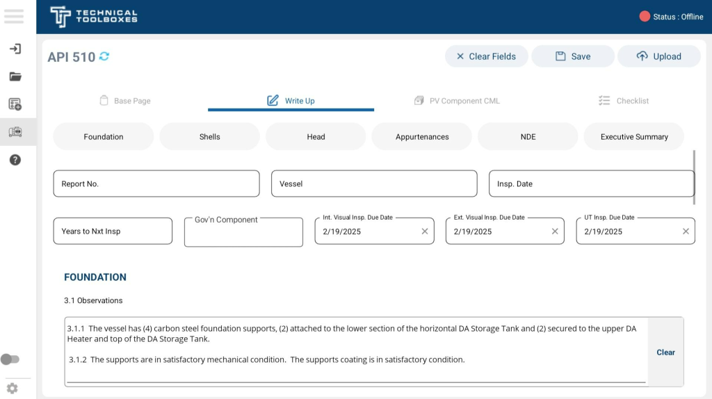
Write-Up Section
The Write-Up section is used to document detailed inspection findings, observations, and recommendations related to pressure vessel components. This section is divided into multiple categories, allowing inspectors to systematically log their assessments based on different vessel parts.
The Write-Up section consists of the following key categories:
Categories
- Foundation
- Shells
- Head
- Appurtenances
- NDE (Non-Destructive Examination)
- Executive Summary
Write-Up Structure
- Report No. – Unique identifier for the inspection report.
- Vessel – Name or identifier of the inspected vessel.
- Inspection Date – Date of the current inspection.
- Years to Next Inspection – Estimate of when the next inspection is due.
- Governing Component – Specifies the main part of the vessel being assessed.
- Internal Visual Inspection Due Date – Scheduled date for the next internal inspection.
- External Visual Inspection Due Date – Scheduled date for the next external inspection.
- Ultrasonic Testing (UT) Inspection Due Date – Scheduled date for the next thickness evaluation.
Quick Navigation Using Top Icons
At the top of the Write-Up section, there are shortcut icons representing each category. Clicking on any icon allows the user to jump directly to that specific section without having to scroll through the entire form. This feature improves efficiency and streamlines the inspection process.
Image Capture & Documentation
Each section of the Write-Up includes an unlimited image capture feature, allowing inspectors to:
- Capture images instantly using the device camera.
- Select images from the gallery to attach relevant photos.
- Rename images for better organization.
- Add descriptions to provide additional details.
Voice-to-Text Feature
- The Write-Up section supports voice-to-text transcription, allowing inspectors to dictate observations and recommendations.
- This feature functions both online and offline, ensuring usability in the field.
User Actions & Navigation
User Actions
- Enter Observations & Recommendations – Inspectors can input their findings in predefined text fields.
- Capture & Upload Photos – Users can attach images to enhance documentation.
- Use Voice-to-Text – Enables hands-free data entry.
- Clear Fields – Removes default or previously entered text.
- Save – Saves progress for later modifications.
- Upload – Submits the Write-Up report to the HUB.
Navigation
- The Write-Up section is structured for easy access to different vessel components.
- Users can navigate back to the Base Page or proceed to the next section: PV Component CML.
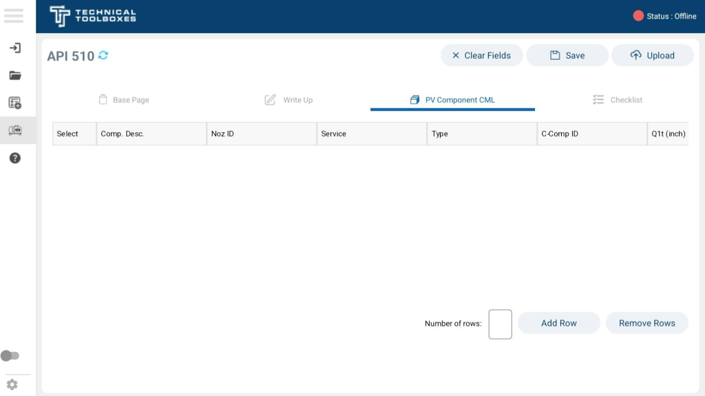
PV Component CML
The PV Component CML (Corrosion Monitoring Locations) section allows users to log and track specific corrosion data points for pressure vessels under API 510 inspections. This section facilitates detailed tracking of component conditions, including thickness measurements, age, and material specifications.
Features
- Component Identification: Users can define components such as shells, heads, and nozzles.
- Corrosion Monitoring: Fields for recording corrosion thickness readings (Q1t, Q2t, Q3t, and Q4t).
- Component Type Selection: Dropdown menus allow classification of components (e.g., C for critical, N for non-critical).
- Material and Age Data: Tracks material specifications, age in years, and schedule details.
- Customizable Row Entries: Users can add or remove rows as needed for additional components.
Fields and Functions
Component Selection
- Component Description: Describes the monitored part (e.g., Shell 1, Head 1, Nozzle ID).
- Type: Dropdown selection between C (Critical) and N (Non-Critical).
- Service: Defines the function of the component within the pressure vessel.
Thickness Readings
- Q1t (inch): First recorded thickness reading.
- Q2t (inch): Second recorded thickness reading.
- Q3t (inch): Third recorded thickness reading.
- Q4t (inch): Fourth recorded thickness reading.
- Minimum: The lowest acceptable thickness threshold.
Additional Component Data
- Age (Y): Tracks the component’s age in years.
- Material Specification: Dropdown for selecting material type.
- Size: Component size details.
- Schedule (Sch): Defines the thickness and structural rating.
User Actions & Navigation
User Actions
- Add Component Data – Users can enter data for each component, including component descriptions, nozzle IDs, service types, and material specifications.
- Select Component Types – Dropdown menus allow for selecting component types such as Shell 1, Shell 2, Head 1, Head 2, or Head 3.
- Enter Thickness Measurements – Inspectors input thickness readings (Q1t, Q2t, Q3t, Q4t) and minimum required thickness values.
- Specify Material Specifications – Users select the appropriate material specification, size, and schedule.
- Add or Remove Rows – Additional rows can be added for multiple components or removed as necessary.
- Clear Fields – Removes all default or previously entered values.
- Save – Stores progress for later modifications.
- Upload – Submits the PV Component CML report to the HUB.
Navigation
- The PV Component CML tab provides a structured layout for documenting corrosion monitoring locations (CMLs) and component details.
- Users can navigate back to the Write-Up tab or proceed to the Checklist section for further inspection.
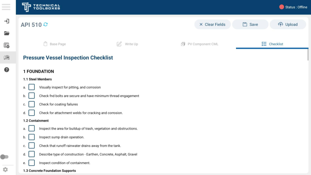
Checklists Section
The Pressure Vessel Inspection Checklist ensures compliance with API 510 standards by covering all critical aspects of a pressure vessel’s condition. This checklist is a single, comprehensive form that includes various inspection areas.
Checklist Coverage
- Foundation – Inspection of steel members, containment structures, and overall foundation integrity.
- Shells – Examination of vessel shells for corrosion, deformation, and structural integrity.
- Shell Appurtenances – Evaluation of nozzles, manways, and external attachments.
- Vessel Jacket (If Applicable) – Inspection of jacketed components, pressure relief vents, and drainage systems.
- Insulation – Assessment of insulation condition, water intrusion, and attachment security.
- Pressure and Temperature Indicators – Verification of gauge calibration, sensor accuracy, and placement.
- ASME & Nameplate Data – Confirmation of nameplate presence, legibility, and compliance with vessel records.
- Vessel Layout Drawings – Review of vessel configuration, modifications, and documentation accuracy.
- UT Thickness Readings – Collection and analysis of ultrasonic thickness measurements to monitor corrosion rates and compliance.
User Actions & Navigation
User Actions
- Mark Inspections as Complete – Inspectors document findings for each checklist category.
- Enter Observations & Findings – Additional notes and comments can be recorded where necessary.
- Attach Supporting Photos – Users can upload images for better documentation.
- Clear Fields – Resets the checklist for fresh data entry.
- Save – Stores checklist progress for later review or modifications.
- Upload – Submits the Pressure Vessel Inspection Checklist to the HUB.
Navigation
- The Checklist tab consolidates all inspection areas into a single form, ensuring a streamlined assessment process.
- Users can navigate back to PV Component CML or any other section before finalizing the report..
Finalizing and Uploading
Once all necessary inspection data has been entered, including component evaluations, checklists, and calculations, the final step is to save and upload the API 510 report to the HUB. This ensures all data is properly stored and accessible for review and compliance checks.
Saving Your Report
Before proceeding with the upload, users must save their report to ensure all inputted data is retained. Click on the Save button at the top-right corner of the screen to store all entered values, notes, and images.
- Tip: If working offline, the report will be stored locally and can be uploaded once an internet connection is available.
Uploading to the HUB
Once the report is saved, follow these steps to upload it to the HUB:
- Log in to the system if not already signed in.
- Click on the Upload button at the top-right of the screen.
- A confirmation pop-up will appear, showing a unique ID number attached to the report. This serves as a reference for tracking and retrieval.
- The system will sync the uploaded report with the HUB, ensuring it is available for review by relevant personnel.
Verifying Report Status in the Report List Tab
After the upload, users should navigate to the Report List tab to verify the report’s status.
- The report status will be updated accordingly (e.g., Uploaded, Pending Review, or Approved).
- Users can locate their report using the ID number generated during the upload process.
By completing this final step, all API 510 inspection reports are securely stored and prepared for compliance verification.
API 570
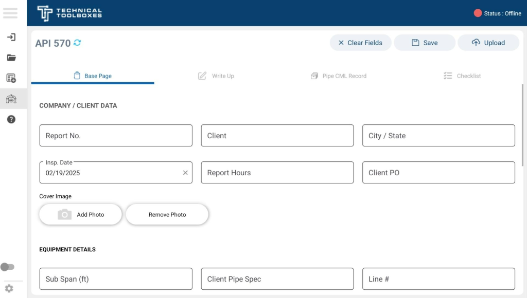
Base Page Section
The Base Page of the API 570 report serves as the initial data entry point for piping system inspections. It captures essential details about the inspection, including client information, pipe specifications, and compliance details in accordance with API 570 standards.
Company / Client Data
This section gathers general information about the inspection request, the client, and the job details.
- Report No. – Unique identifier assigned to the inspection report.
- Client – Name of the company or client requesting the inspection.
- City / State – Location details of the inspection site.
- Inspection Date – Date when the inspection was conducted (Default: 02/19/2025).
- Report Hours – Total hours logged for the inspection.
- Client PO – Purchase order reference for the inspection services.
Equipment Details
This section provides technical specifications of the piping system under inspection.
- Sub Span (ft) – Distance between pipe support points.
- Client Pipe Spec – Specific piping material and standard as per the client’s request.
- Line # – Unique identifier for the pipe segment being inspected.
- Location – Physical site or plant section where the pipeline is situated.
- Service – Describes the fluid or gas the pipeline carries (e.g., Steam, Gas, Oil).
- Year Built – Construction year of the piping system.
- Construction Code – Governing design code for compliance (e.g., ASME B31.1, B31.3).
- Line Rating – Pressure classification of the piping (e.g., Class 150, 300).
- Design Pressure (psi) – Maximum pressure the piping system is designed to withstand.
- Design Temperature (°F) – Maximum operating temperature the system can handle.
- MDMT (°F) – Minimum Design Metal Temperature, ensuring safe operation in low temperatures.
- Material Type – Specifies the material used (e.g., Carbon Steel, Stainless Steel).
- Nominal Diameter (in) – Internal diameter of the pipe.
- Operating Pressure (psi) – The pressure at which the system is currently running.
- Operating Temperature (°F) – The working temperature of the pipeline.
- API Class – Classification based on risk and design criteria (e.g., Class 1, 2, 3).
- ASME Category – Defines the category per ASME code (e.g., Normal).
- Insulation Type – Describes the type of insulation (e.g., Calcium Silicate, None).
- Insulation Thickness (in) – Thickness of the insulating material.
- Corrosion Allowance (CA) (in) – Expected loss of material due to corrosion over time.
Reference Data
This section provides reference thickness values for Pipe/Nozzle Practical Tmin, ensuring the user has quick access to acceptable minimum thickness limits.
- Tmin Table – Displays the minimum required thickness for various pipe sizes.
User Actions & Navigation
User Actions
- Enter Data – Users input all relevant inspection details in the designated fields.
- Attach Cover Image – Upload a representative image of the piping system.
- Remove Photo – Delete the uploaded image if needed.
- Clear Fields – Resets all input fields to default settings.
- Save – Saves progress for future editing.
- Upload – Submits the Base Page data to the HUB for record-keeping.
Navigation
- The Base Page is the starting point of the API 570 inspection report.
- Users can proceed to the next section (Write-Up) via the top navigation bar.
- Ensures that all fundamental piping details are recorded before advancing to condition assessments.
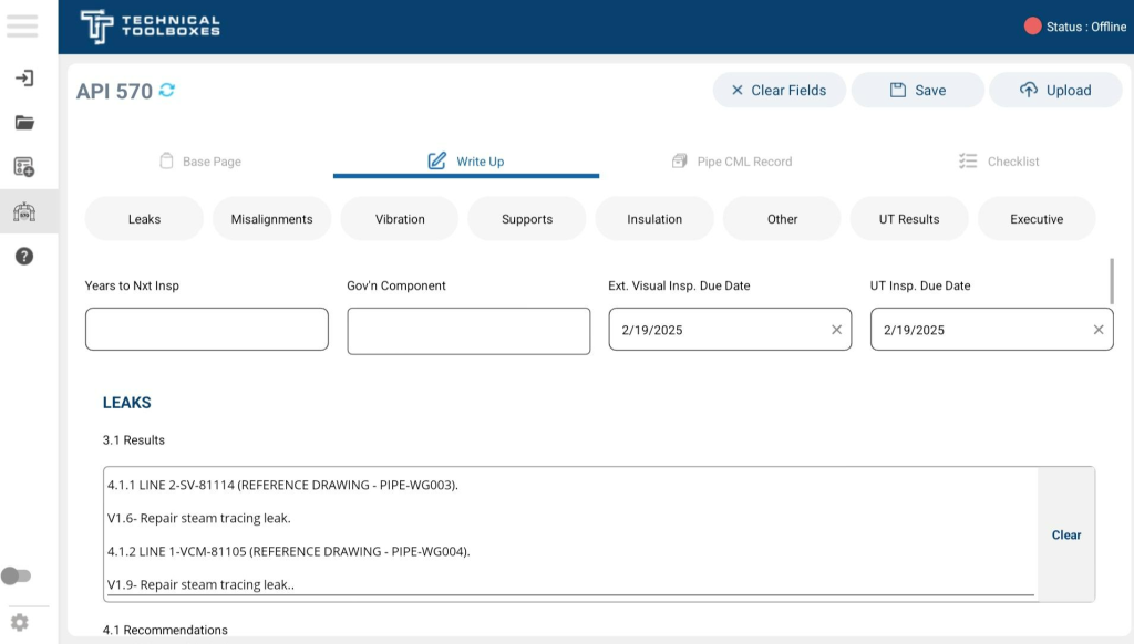
Write-Up Section
The Write-Up section is used to document detailed inspection findings, observations, and recommendations related to piping systems under API 570 guidelines. This section is structured to allow inspectors to systematically record assessments for various aspects of pipeline integrity and functionality.
Categories in the Write-Up Section
The Write-Up section is divided into multiple key categories, enabling a thorough evaluation of different piping conditions:
- Leaks – Identification and documentation of leaks in the system.
- Misalignments – Any pipeline shifts or improper alignments that could affect performance.
- Vibration – Assessment of excessive vibration leading to potential failures.
- Supports – Condition of pipeline support structures (hangers, brackets, shoes, etc.).
- Insulation – Inspection of insulation material for degradation or missing coverage.
- Other – Additional notes on anomalies not covered in previous sections.
- UT Results – Recording ultrasonic thickness (UT) measurements for corrosion evaluation.
- Executive Summary – Final summary and key recommendations for corrective actions.
Write-Up Structure
- Report No. – Unique identifier assigned to the inspection report.
- Inspection Date – Date of the current piping system inspection.
- Years to Next Inspection – Estimated time before the next scheduled inspection.
- Governing Component – Primary component of the piping system being evaluated.
- External Visual Inspection Due Date – Date for the next external inspection.
- Ultrasonic Testing (UT) Inspection Due Date – Scheduled date for thickness assessment.
Quick Navigation Using Top Icons
- The top menu of the Write-Up section provides quick-access icons for each category.
- Clicking an icon will take the inspector directly to the relevant section, reducing scrolling and improving workflow efficiency.
Image Capture & Documentation
Each category allows unlimited image attachments, enabling comprehensive visual documentation for each inspection finding. Features include:
- Capture Images Instantly – Take photos directly using the device camera.
- Upload from Gallery – Select and attach relevant images from stored files.
- Rename Images – Organize attachments with meaningful file names.
- Add Descriptions – Provide details explaining the image contents.
Voice-to-Text Feature
The Write-Up section supports hands-free documentation using voice-to-text transcription. This allows inspectors to dictate their observations instead of manually typing.
- Works both online and offline, ensuring usability in remote locations.
- Supports multiple languages for diverse teams.
User Actions & Navigation
User Actions
- Enter Observations & Recommendations – Input findings directly into predefined text fields.
- Capture & Upload Photos – Attach supporting images to improve documentation.
- Use Voice-to-Text – Utilize speech recognition for hands-free data entry.
- Clear Fields – Reset text fields to remove previous inputs.
- Save – Store progress for later editing.
- Upload – Submit the Write-Up report to the HUB for record-keeping.
Navigation
- The Write-Up section provides structured access to pipeline integrity details.
- Users can navigate back to the Base Page or proceed to the next section: Pipe CML Record.

Pipe CML Record Section
The Pipe CML Record (Corrosion Monitoring Locations) section is designed for tracking corrosion and material integrity in pipeline systems under API 570 guidelines. This section allows inspectors to log thickness measurements, monitor component conditions, and maintain a structured record of piping data over time.
Features
- Component Identification – Users define components such as pipeline sections, fittings, and welded joints.
- Corrosion Monitoring – Dedicated fields for corrosion thickness readings (Q1t, Q2t, Q3t, Q4t).
- Component Type Selection – Dropdown menus allow classification of pipeline components.
- Material & Age Data – Tracks material specifications, pipe age (years), and schedule ratings.
- Customizable Row Entries – Inspectors can add or remove rows as needed for additional pipelines or fittings.
Fields and Functions
Component Selection
- Line Number – Identifies the inspected pipeline segment.
- Component Description – Defines the monitored part (e.g., Elbow, Tee, Straight Pipe).
- Type – Dropdown selection between C (Critical) and N (Non-Critical).
- Service – Defines the function of the pipeline (e.g., Steam, Process Fluid).
Thickness Readings
- Q1t (inch) – First recorded thickness measurement.
- Q2t (inch) – Second recorded thickness measurement.
- Q3t (inch) – Third recorded thickness measurement.
- Q4t (inch) – Fourth recorded thickness measurement.
- Minimum – The lowest acceptable thickness threshold before requiring corrective action.
Additional Component Data
- Age (Y) – Tracks the component’s age in years.
- Material Specification – Dropdown for selecting material type (e.g., Carbon Steel, Stainless Steel).
- Size – Nominal diameter of the pipeline section.
- Schedule (Sch) – Defines the thickness and pressure rating of the pipe.
User Actions & Navigation
User Actions
- Add Component Data – Users enter details such as line numbers, component descriptions, and service types.
- Select Component Types – Dropdown menus allow selection of component types like Pipe, Elbow, or Tee.
- Enter Thickness Measurements – Inspectors input thickness readings (Q1t, Q2t, Q3t, Q4t) and minimum allowable values.
- Specify Material Specifications – Users select the appropriate material type, size, and schedule for each component.
- Add or Remove Rows – Additional rows can be inserted for multiple pipeline sections or fittings.
- Clear Fields – Removes all default or previously entered values.
- Save – Stores progress for later modifications.
- Upload – Submits the Pipe CML Record report to the HUB for record-keeping.
Navigation
- The Pipe CML Record tab provides a structured layout for documenting corrosion monitoring locations (CMLs) and component details.
- Users can navigate back to the Write-Up tab or proceed to the Checklist section for final inspection.
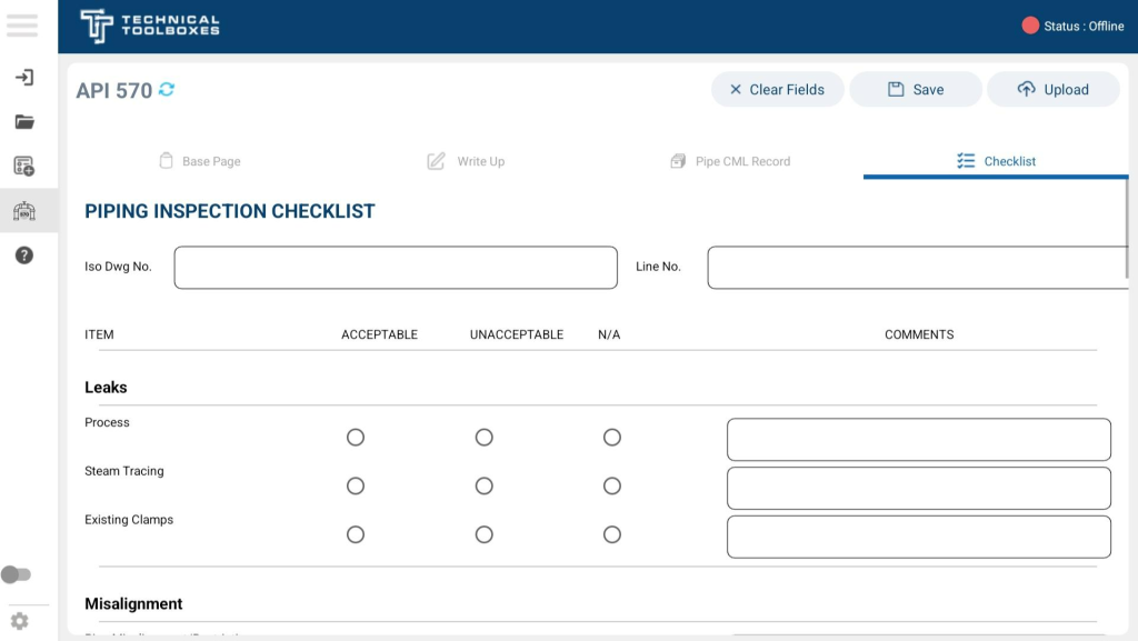
Checklist Section
The Piping Inspection Checklist ensures compliance with API 570 standards by covering all critical aspects of a pipeline system’s condition. This checklist is a single, comprehensive form that includes various inspection areas for identifying pipeline integrity issues.
Checklist Coverage
- Leaks – Inspection of process leaks, steam tracing leaks, and existing clamps for containment failures.
- Misalignment – Evaluation of pipe restrictions and expansion joint alignment issues.
- Vibration – Assessment of excessive overhung weight, support stability, and threaded connections.
- Supports – Examination of pipe shoes, hanger distortion, spring hangers, bracing, brackets, slide plates, and support corrosion.
- Corrosion – Identification of coating failures, crevice corrosion, soil-to-air interface issues, insulation interface corrosion, and biological growth.
- Insulation – Verification of insulation condition, missing jacketing, sealing deterioration, bulging, and broken/missing banding.
User Actions & Navigation
User Actions
- Mark Inspections as Complete – Inspectors document findings for each checklist category, marking items as Acceptable, Unacceptable, or Not Applicable.
- Enter Observations & Findings – Additional notes and comments can be recorded where necessary.
- Attach Supporting Photos – Users can upload images to enhance documentation and provide visual evidence.
- Clear Fields – Resets the checklist for fresh data entry.
- Save – Stores checklist progress for later review or modifications.
- Upload – Submits the Piping Inspection Checklist to the HUB for record-keeping.
Navigation
- The Checklist tab consolidates all inspection areas into a single structured form, ensuring a streamlined pipeline integrity assessment.
- Users can navigate back to the Pipe CML Record tab or proceed to finalize the API 570 report before submission.
Finalizing and Uploading API 570 Reports
With all inspection data recorded—including pipe thickness measurements, checklists, and calculations—the final step is to save and upload the API 570 report to the HUB for compliance and record-keeping.
Saving Your Report
Before uploading, users must save their work to ensure all data is preserved. Click on the Save button in the top-right corner to store all entered measurements, notes, and supporting images.
- Tip: If offline, the report will be stored locally and can be uploaded when the device is back online.
Uploading to the HUB
Once the report is saved, follow these steps to upload it:
- Log in to the system if not already signed in.
- Click on the Upload button in the top-right corner.
- A confirmation pop-up will appear, displaying a unique ID number for the uploaded report, which serves as a reference.
- The system will automatically sync the report with the HUB, making it available for compliance review.
Verifying Report Status in the Report List Tab
After uploading, users should go to the Report List tab to confirm the report’s submission.
- The report status will reflect its current state (e.g., Uploaded, Pending Review, or Approved).
- Users can search for their report using the ID number assigned during the upload process.
Completing this step ensures that all API 570 inspection reports are accurately stored, properly documented, and ready for compliance verification.