
Introduction
The buoyancy of a pipeline depends upon the weight of the pipe, the weight of the volume of water displaced by the pipe, the weight of the liquid load carried by the pipe and the weight of the backfill. As a conservative analytical practice, consider the pipeline empty for two reasons; so, the weight of the liquid will be considered as an additional safety factor and the possibility of the pipeline not being in use during a period.
This calculation is used to determine the buoyance of the specified underwater pipe based on the required thickness of concrete coating to counter the buoyancy forces.
The calculation does not account/allow for depth of water or burial. PLTB input is unit weight of water.
Determine Bare Pipe Weight
W_{pipe}=10.68(D-t)t\,[lbs/ft],\,where
W_{pipe}=10.68(D-t)t\,[lbs/ft],\,where𝐷 − Pipe outside diameter (in)
𝑡 − Pipe wall thickness (in)
Determine Total Volume of Pipe in Air Including Corrosion and Concrete Coating
V_{total}=\frac{\pi(D+2(t_{corr}+t_{con}))^2}{4(144)}[ft^3],\,where
V_{total}=\frac{\pi(D+2(t_{corr}+t_{con}))^2}{4(144)}[ft^3],\,where𝑡𝑐𝑜𝑟𝑟 = Corrosion coating thickness (in)
𝑡𝑐𝑜𝑛 = Concrete coating thickness (in)
Determine Volume of Corrosion Coating
V_{corr}=\frac{\pi (D+2t_{corr})^2}{4(144)}-\frac{\pi D^2}{4(144)}[ft^3],\,where
V_{corr}=\frac{\pi (D+2t_{corr})^2}{4(144)}-\frac{\pi D^2}{4(144)}[ft^3],\,whereDetermine Volume of Concrete Coating
V_{con}=V_{total}-V_{corr}-\frac{\pi D^2}{4(144)}[ft^3]
V_{con}=V_{total}-V_{corr}-\frac{\pi D^2}{4(144)}[ft^3]Determine Total Weight of Pipe in Air, Including Weight of Corrosion and Concrete Coating
W_{total}=W_{pipe}+V_{corr}\rho_{corr}+V_{con}\rho_{con}\,[lb/ft^3],\,where
W_{total}=W_{pipe}+V_{corr}\rho_{corr}+V_{con}\rho_{con}\,[lb/ft^3],\,where𝜌𝑐𝑜𝑟𝑟 = Corrosion coating specific weight (lb/ft3)
𝜌𝑐𝑜𝑛 = Concrete coating specific weight (lb/ft3)
Determine Weight of Displaced Water
W_{water}=V_{total}\rho_{w}\,[lbs/ft],\,where
W_{water}=V_{total}\rho_{w}\,[lbs/ft],\,where𝜌𝑤 = Specific weight of water (lb/ft3)
Determine the Difference
F=W_{total}-W_{water}[lbs/ft]
F=W_{total}-W_{water}[lbs/ft]Determine Bulk Specific Gravity
B=\frac{W_{total}}{W_{water}}
B=\frac{W_{total}}{W_{water}}Case Guide
Part 1: Create Case
- Select the Buoyancy Analysis & Concrete Coating Requirements application from the Design & Stress Analysis Module
- To create a new case, click the “Add Case” button
- Enter Case Name, Location, Date and any necessary notes.
- Fill out all required Parameters.
- Make sure the values you are inputting are in the correct units.
- Click the CALCULATE button to overview results.
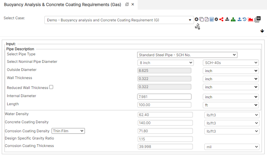
Input Parameters
- Nominal Pipe Size (in):(0.625” – 48”)
- Wall Thickness (in):(0.068”- >2”)
- Pipe grade: (24000psi-80000psi) (if unknown use Grade A 24000)
- Pipe length (ft/joint)
- Water Density: (59 – 64) (lbs./ft³)
- Concrete Coating Density: (50- 170) (lbs./ft³)
- Corrosion Coating Density: (50 – 100) (lbs./ft³)
- Design Specific Gravity Ratio
- Corrosion Coating Thickness (in): (1mil – 50mils)
Part 2: Outputs/Reports
- If you need to modify an input parameter, click the CALCULATE button after the change.
- To SAVE, fill out all required case details then click the SAVE button.
- To rename an existing file, click the SAVE As button. Provide all case info then click SAVE.
- To generate a REPORT, click the REPORT button.
- The user may export the Case/Report by clicking the Export to Excel icon.
- To delete a case, click the DELETE icon near the top of the widget.
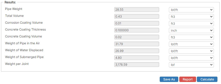
Results
- Pipe weight (lbs/ft)
- Total Volume (ft³)
- Corrosion Coating Volume (ft³)
- Concrete Coating Thickness: (0.25” – 8.5”) (in)
- Weight of Pipe in Air: (21 – 1750) (lbs/ft)
- Weight of Water Displaced: (3 – 1600) (lbs/ft)
- Weight of Submerged Pipe: (2l – 250) (lbs/ft)
- Weight per Joint: (800 – 70000) (lbs/ft)
References
- ASME B31.8 – Gas Transmission and Distribution Piping Systems
- API 5L, API 5LS and API 5LX – Specification of Pipe Grade
- ASTM – Various – Weld Joint Factor
- CFR Code Part 192
- USDA-SCS Modified (Permissible Velocity of Water and Soil Erodibility)
- FHWA-HEC
- Pipeline Rules of Thumb Handbook
- Timoshenko, S – Theory of Elasticity Anchor Force
FAQ
-
Restrained versus Unrestrained Pipe (Difference in Gas vs. Liquid)?
ASME B31.4 liquid and B31.8 gas codes include calculations for the net longitudinal compressive stress that must be applied only for a restrained line that equates to a low (less than 2%) longitudinal strain. This stress status is characteristic to underground pipelines located some distance away from above ground piping facilities.
Unrestrained lines means those above ground sections of piping without axial restraint as with buried pipe with soil. In others words the soil exerts substantial axial restraint, but not fully restrained. Check Out
-
What is the Maximum Span Length of rev1?
Regarding span factors with and without water are based on bending stress and deflection. Larger diameter pipe spans require saddles for stability. Many standards that require pipes to be filled with water are based on bending and shear stresses not to exceed 1,500 psi and a deflection between supports not exceed 0.1 inches. Check Out
-
What is the model used for Thrust at Blow-Off?