
Introduction
This application uses the affinity laws to calculate the volume capacity, head when the speed of the impeller is changed. Understanding the ratio of specific heat for the gas being used in the compressor may present challenges.
Gas volume flow is proportional to the impeller rotation speed: \frac{Q_1}{Q_2}=\frac{n_1}{n_2}
\frac{Q_1}{Q_2}=\frac{n_1}{n_2}Head is proportional to the square of the impeller rotation speed: \frac{H_1}{H_2}=\left( \frac{n_1}{n_2}\right)^2
\frac{H_1}{H_2}=\left( \frac{n_1}{n_2}\right)^2Brake horsepower is proportional to the cube of the impeller rotation speed: \frac{BHP_1}{BHP_2}=\left( \frac{n_1}{n_2} \right)^3
\frac{BHP_1}{BHP_2}=\left( \frac{n_1}{n_2} \right)^3Where:
𝑄1 − Initial Flow (𝑀𝑀𝑆𝐶𝐹𝐷)
𝑄2 − Final Flow (𝑀𝑀𝑆𝐶𝐹𝐷)
𝐻1 − Initial Compressor head (ft*lbf/lbm)
𝐻2 − Final Compressor head (ft*lbf/lbm)
𝐵𝐻𝑃1 − Initial Brake Horsepower (HP)
𝐵𝐻𝑃2 − Final Brake Horsepower (HP)
𝑛1 − Initial Rotational Speed (rpm)
𝑛2 − Final Rotational Speed (rpm)
CNGA/GPSA Compressibility Factor Approximation:
Z=\frac{1}{\left[1+\left(\frac{3.444\times10^5P\times10^{1.785G}}{T_f^{3.825}} \right)\right]}
Z=\frac{1}{\left[1+\left(\frac{3.444\times10^5P\times10^{1.785G}}{T_f^{3.825}} \right)\right]}Where:
𝑍 − Compressibility Factor
𝑃 − Pressure
𝑇𝑓 − Gas Flowing Temperature (°𝑅)
Case Guide
Part 1: Create Case
- Select the Fan Laws application from the Compressor Module
- To create a new case, click the “Add Case” button
- Enter Case Name, Location, Date and any necessary notes.
- Fill out all required Parameters.
- Make sure the values you are inputting are in the correct units.
- Click the CALCULATE button to overview results.
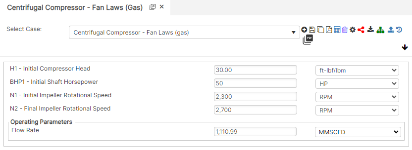
Input Parameters
- H1 – Initial Compressor Head (ft*lbf/lbm)
- BHP1 – Initial Shaft Horsepower (HP)
- N1 – Initial Impeller Rotational Speed (rpm)
- N2 – Final Impeller Rotational Speed (rpm)
- Flow Rate (MMSCFD)
Part 2: Outputs/Reports
- If you need to modify an input parameter, click the CALCULATE button after the change.
- To SAVE, fill out all required case details then click the SAVE button.
- To rename an existing file, click the SAVE As button. Provide all case info then click SAVE.
- To generate a REPORT, click the REPORT button.
- The user may export the Case/Report by clicking the Export to Excel icon.
- To delete a case, click the DELETE icon near the top of the widget.
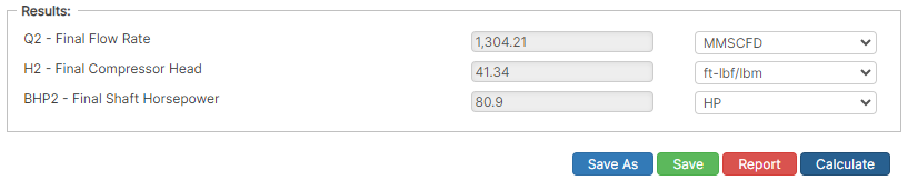
Results
- Q2 – Final Flow Rate (MMSCFD)
- H2 – Final Compressor Head (ft*lbf/lbm)
- BHP2 – Final Shaft Horsepower (HP)
References
- Engineering Data Book, Volume 1, Gas Processors Suppliers Association, Tenth Edition
- Compressor Station Operation, Book T-2, GEOP, American Gas Association (A.G.A.)
- Compressor Selection and Sizing, Royce N. Brown, Second Edition, Gulf Professional Publishing