
Introduction
This application uses gas velocity and flow rates to determine the minimum required pipe diameter for station piping.
Gas Velocity
v=\frac{127.3\times10^3QP_bT_fZ}{D^2P_fT_b}
v=\frac{127.3\times10^3QP_bT_fZ}{D^2P_fT_b}Pipe Diameter
D=\sqrt{\frac{127.3\times10^3QP_bT_fZ}{vP_fT_b}}
D=\sqrt{\frac{127.3\times10^3QP_bT_fZ}{vP_fT_b}}Wall Thickness
Wt=\frac{P\left( \frac{127.3\times10^3QP_bT_fZ}{vP_fT_b} \right)^{0.5}}{2S}FET
Wt=\frac{P\left( \frac{127.3\times10^3QP_bT_fZ}{vP_fT_b} \right)^{0.5}}{2S}FETWhere:
𝑣 − Gas Velocity (ft/min)
𝑄 − Flow Rate (MMCFD)
𝑊𝑡 − Wall Thickness (in)
𝑃 − Design Pressure (psi)
𝐹 − Design Factor
𝐸 − Longitudinal Joint Factor
𝑇 − Temperature Derating Factor
𝑃𝑏 − Base Pressure (psia)
𝑇𝑓 − Flowing Temperature (°R)
𝑍 − Compressibility Factor
𝐷 − Internal Pipe Diameter (in)
𝑃𝑓 − Flowing Pressure (psia)
𝑇𝑏 − Base Temperature (°R)
Note: Gas velocity in piping should not exceed 2000(ft/min)
CNGA/GPSA Compressibility Factor Approximation:
Z=\frac{1}{\left[1+\left(\frac{3.444\times10^5P\times10^{1.785G}}{T_f^{3.825}} \right)\right]}
Z=\frac{1}{\left[1+\left(\frac{3.444\times10^5P\times10^{1.785G}}{T_f^{3.825}} \right)\right]}Where:
𝑍 − Compressibility Factor
𝑃 − Pressure
𝑇𝑓 − Gas Flowing Temperature (°𝑅)
This approximation will produce results sufficiently accurate for preliminary calculations.
Brake Horsepower
BHP=\frac{HP}{n_m}
BHP=\frac{HP}{n_m}Where:
𝑛𝑚 − Mechanical Efficiency 𝑛𝑚 = 0.95/0.98
Case Guide
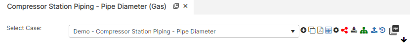
Part 1: Create Case
- Select the Compressor Station Piping application from the Compressor Module
- To create a new case, click the “Add Case” button
- Enter Case Name, Location, Date and any necessary notes.
- Fill out all required Parameters.
- Make sure the values you are inputting are in the correct units.
- Click the CALCULATE button to overview results.
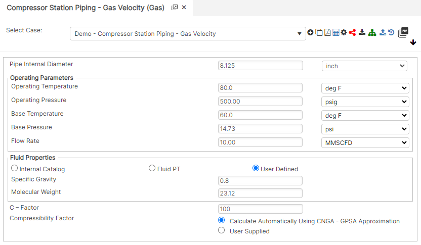
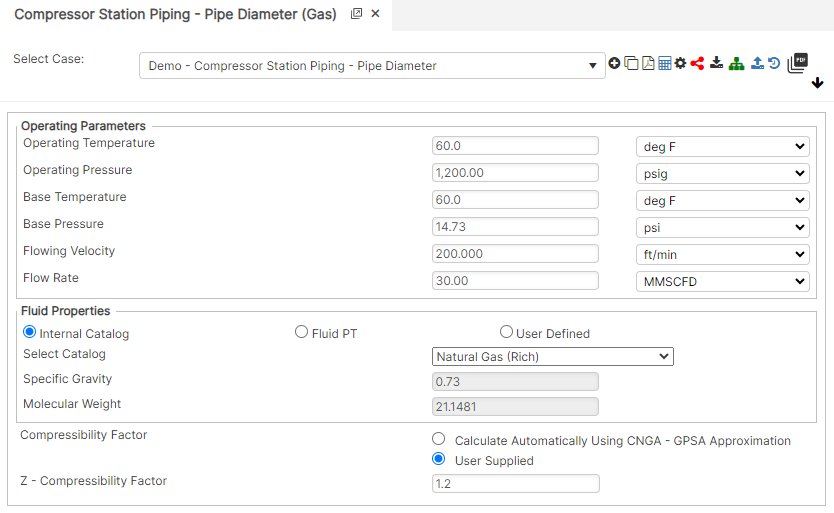
Input Parameters
- Pipe Internal Diameter (in)
- Operating Temperature (°F)
- Operating Pressure (psig)
- Base Temperature (°F)
- Base Pressure (psi)
- Capacity/Required Flow Rate (MMSCFD)
- Gas Specific Gravity (Relative to air)
- Gas Molecular Weight
- C – Factor
- Compressibility Factor
- Z – Compressibility Factor
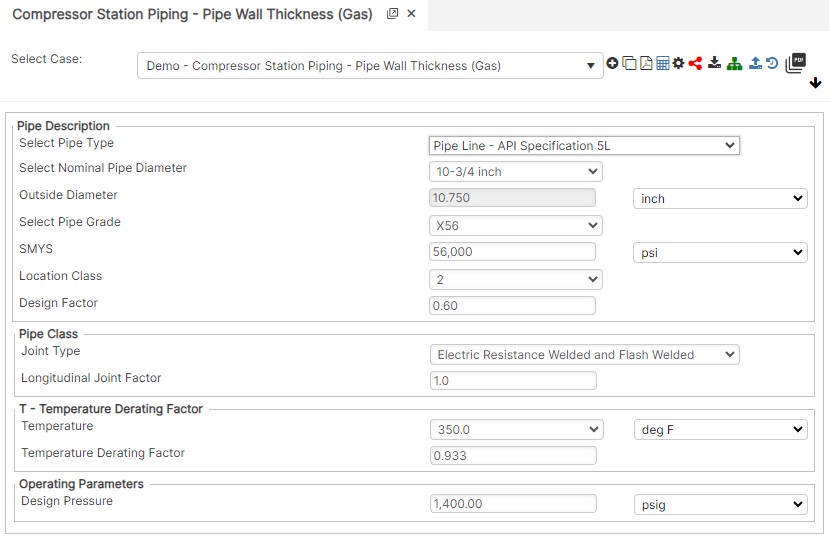
- Outside Diameter (in)
- SMYS (psi)
- Design Factor
- Joint Type
- Temperature Derating Factor
- Design Pressure (psig)
Gas Velocity
Pipe Diameter
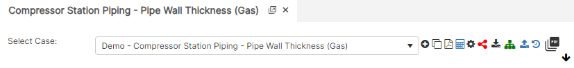
Wall Thickness
Part 2: Outputs/Reports
- If you need to modify an input parameter, click the CALCULATE button after the change.
- To SAVE, fill out all required case details then click the SAVE button.
- To rename an existing file, click the SAVE As button. Provide all case info then click SAVE.
- To generate a REPORT, click the REPORT button.
- The user may export the Case/Report by clicking the Export to Excel icon.
- To delete a case, click the DELETE icon near the top of the widget.
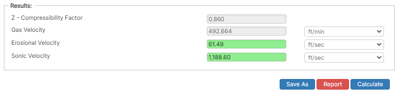
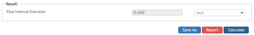
Results
- Z – Compressibility Factor
- Gas Velocity (ft/min)
- Erosional Velocity (ft/min)
- Sonic Velocity (ft/min)
- Pipe Internal Diameter (in)
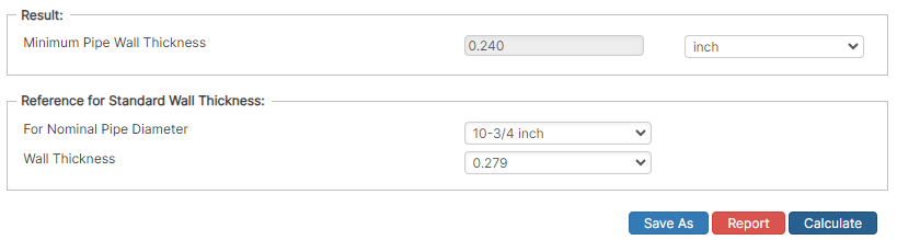
- Minimum Pipe Wall Thickness (in)
Gas Velocity
Pipe Diameter
Wall Thickness
References
- Engineering Data Book, Volume 1, Gas Processors Suppliers Association, Tenth Edition
- Compressor Station Operation, Book T-2, GEOP, American Gas Association (A.G.A.)
- Compressor Selection and Sizing, Royce N. Brown, Second Edition, Gulf Professional Publishing