
Introduction
Based on SW Research Report calculations for the blowdown time and mass of gas vented to atmosphere to a piping system. Accurate to within a few percent.
Blowdown time is impacted through constricting valve changes from sonic (choked) flow to subsonic. This is because of the pressure ratio across the valve is unknow.
V_o = V_p + V_{\text{sys}} \~\ V_{\text{sys}} = V_{s(i1)} + V_{s(i2)} + V_{s(i3)} + \ldots
V_o = V_p + V_{\text{sys}} \\~\\ V_{\text{sys}} = V_{s(i1)} + V_{s(i2)} + V_{s(i3)} + \ldots
Where:
𝑉𝑜 − Total Volume (ft3)
𝑉𝑠𝑦𝑠 − Volume of system (ft3)
V_p=\bigg(\frac{1}{144}\bigg)\bigg(\frac{\pi}{4}\bigg)L_pD_{pi}^2
V_p=\bigg(\frac{1}{144}\bigg)\bigg(\frac{\pi}{4}\bigg)L_pD_{pi}^2𝑉𝑃 − Volume of Mainline Pipe (ft3)
𝐿𝑝 − Mainline Pipe Length (in)
𝐷𝑝𝑖 − Mainline Pipe Internal Diameter (in)
V_{s(i)} = \left(\frac{\pi}{4}\right) \left(\frac{D_{s(i)}}{12} – \frac{2wt_{s(i)}}{12}\right) \left(\frac{D_{s(i)}}{12} – \frac{2wt_{s(i)}}{12}\right) L_{s(i)}
V_{s(i)} = \left(\frac{\pi}{4}\right) \left(\frac{D_{s(i)}}{12} - \frac{2wt_{s(i)}}{12}\right) \left(\frac{D_{s(i)}}{12} - \frac{2wt_{s(i)}}{12}\right) L_{s(i)}
𝑉𝑠(𝑖) − Volume of individual pipes (ft3)
𝐷𝑠(𝑖) − Diameter of individual pipes (in)
𝑤𝑡𝑠(𝑖) − Wall Thickness of individual pipes (in)
𝐿𝑠(𝑖) − Length of individual pipes (mi)
fl / D \text{ Factor} = f\left( \frac{L}{\left(\frac{d_i}{ 12}\right)} \right)
fl / D \text{ Factor} = f\left( \frac{L}{\left(\frac{d_i}{ 12}\right)} \right)
𝑓 − Friction Factor (Sum of flow friction through all diameters of blowdown piping)
𝐿 − Blowdown Pipe Length (ft)
𝑑𝑖 − Internal Diameter of Blowdown Pipe (in)
A_r=\frac{\pi D_r^2}{4}
A_r=\frac{\pi D_r^2}{4}𝐴𝑟 − Cross−Sectional Area of Choke (in2)
𝐷𝑟 − Diameter of Choked Flow Point (in)
A_p=\frac{\pi d_i^2}{4}
A_p=\frac{\pi d_i^2}{4}𝐴𝑝 – Cross−Sectional Area of Blowdown Pipe (in2)
𝑑𝑖 − Internal Diameter of Blowdown Pipe (in)
𝑅𝐴 − Ratio of Choked Flow Area to Pipe Flow Area
R_A = \left(\frac{d_i}{D_r}\right)^2 \text{ or } \,R_A = \frac{A_r}{A_p}
R_A = \left(\frac{d_i}{D_r}\right)^2 \text{ or } \,R_A = \frac{A_r}{A_p}
𝑐𝑓 − Coefficient of Blowdown Loss (Sum of loss for𝑅𝐴/𝑓𝑙𝑑)
P_{si} = 45 + 25(cf) + 5(cf)^2 \~\ P_{IN} = P_{in} + P_b \~\ P_F = P_f + P_b \~\P_{\text{cavg}} = \frac{P_{IN} + P_F}{2} \~\ P_{\text{savg}} = \frac{P_{si} + P_F}{2}
P_{si} = 45 + 25(cf) + 5(cf)^2 \\~\\ P_{IN} = P_{in} + P_b \\~\\ P_F = P_f + P_b \\~\\P_{\text{cavg}} = \frac{P_{IN} + P_F}{2} \\~\\ P_{\text{savg}} = \frac{P_{si} + P_F}{2}
𝑃𝑠𝑖 − Initial Subsonic Pressure (psi)
𝑃𝑖𝑛 − Initial Pressure (psi)
𝑃𝑓 − Final Pressure (psi)
𝑃𝑏 − Base Pressure (psi)
𝑃𝑐𝑎𝑣𝑔 − Average Sonic Pressure (psi)
𝑃𝑠𝑎𝑣𝑔 − Average Subsonic Pressure (psi)
From the SWRI – SIMPLIFIED BLOWDOWN CALCULATIONS FOR PRESSURIZED GAS SYSTEMS Technical Report you can find tables and equations to complete many of the remaining calculations in this module.
A_c = \sqrt{\gamma g Z R T} \~\ A_{cc} = A_c P_{\text{cavg}} \~\ A_{cs} = A_c P_{\text{savg}}
A_c = \sqrt{\gamma g Z R T} \\~\\ A_{cc} = A_c P_{\text{cavg}} \\~\\ A_{cs} = A_c P_{\text{savg}}
𝛾 − Can be found in table I of the SWRI Technical report mentioned above.
𝑅 − Universal gas constant (𝑈𝑟 = 1545) divided by the molecular weight 𝑀𝑤
𝐴𝑐 − Acoustic Velocity (ft/sec)
𝐴𝑐𝑐 − Sonic Acoustic Velocity (ft/sec)
𝐴𝑐𝑠 − Subsonic Acoustic Velocity (ft/sec)
𝑔 − Gravitational constant, 32.2
𝑍 − Compressibility Factor
𝑇 − Absolute Temperature of the gas(°R)
ce = \frac{\gamma – 1}{2\gamma}
ce = \frac{\gamma - 1}{2\gamma}
𝑐𝑒−Isentropic Compression Exponent
M_u = \left( \frac{2}{\gamma – 1} \right) \left( \frac{\gamma + 1}{2} \right)^{\frac{\gamma + 1}{2(\gamma – 1)}}
M_u = \left( \frac{2}{\gamma - 1} \right) \left( \frac{\gamma + 1}{2} \right)^{\frac{\gamma + 1}{2(\gamma - 1)}}
𝑀𝑢𝑐 & 𝑀𝑢𝑠 − Thermodynamic multiplier to account for compressibility, Table II (choked and subsonic)
T_c = \frac{c_f V_o M_{uc}}{A_f A_{cc}} \left( P_{IN}^{ce}\big)\big( \left( P_F^{ce} – P_{IN}^{ce} \right) \right)
T_c = \frac{c_f V_o M_{uc}}{A_f A_{cc}} \left( P_{IN}^{ce}\big)\big( \left( P_F^{ce} - P_{IN}^{ce} \right) \right)
𝑇𝑐 − Choked Blowdown Time (sec)
T_s = \frac{c_f V_o M_{us}}{A_f A_{cs}} \left(P_{IN}^{ce} \big)\big(\left(P_F^{ce} – P_{IN}^{ce}\right)\right)
T_s = \frac{c_f V_o M_{us}}{A_f A_{cs}} \left(P_{IN}^{ce} \big)\big(\left(P_F^{ce} - P_{IN}^{ce}\right)\right)
𝑇𝑠 − Subsonic Blowdown Time (sec)
T_{Total}=T_c+T_s
T_{Total}=T_c+T_s𝑇𝑇𝑜𝑡𝑎𝑙 − Total Blowdown Time (min)
\Delta M_c = \frac{P_{IN} V_o 144}{Z R T} \left[1 – \left(\frac{P_F}{P_{IN}}\right)^{\frac{1}{\gamma}}\right] \~\ V_{\text{Loss}} = \frac{\Delta M_c}{0.0457}
\Delta M_c = \frac{P_{IN} V_o 144}{Z R T} \left[1 - \left(\frac{P_F}{P_{IN}}\right)^{\frac{1}{\gamma}}\right] \\~\\ V_{\text{Loss}} = \frac{\Delta M_c}{0.0457}
Δ𝑀𝑐 − Mass Loss (lbs)
𝑉𝐿𝑜𝑠𝑠 − Gas Volume Lost (MSCF)
Case Guide
Part 1: Create Case
- Select the Gas Pipeline Blowdown – Semiemperical Model – Report No. 87-2 application from the Testing Module
- To create a new case, click the “Add Case” button
- Enter Case Name, Location, Date and any necessary notes.
- Fill out all required Parameters.
- Make sure the values you are inputting are in the correct units.
- Click the CALCULATE button to overview results.
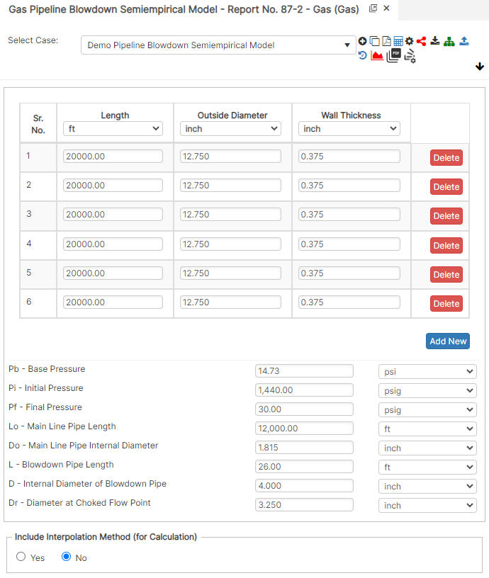
Input Parameters
- Pb – Base Pressure (psia)
- Pi – Initial Pressure (psig)
- Pf – Final Pressure (psig)
- Lo – Main Line Pipe Length (ft)
- Do – Main Line Pipe Internal Diameter (in)
- L – Blowdown Pipe Length( ft)
- D – Internal Diameter of Blowdown (in)
- Dr – Diameter at Choke Flow Point (in)
Part 2: Outputs/Reports
- If you need to modify an input parameter, click the CALCULATE button after the change.
- To SAVE, fill out all required case details then click the SAVE button.
- To rename an existing file, click the SAVE As button. Provide all case info then click SAVE.
- To generate a REPORT, click the REPORT button.
- The user may export the Case/Report by clicking the Export to Excel icon.
- To delete a case, click the DELETE icon near the top of the widget.
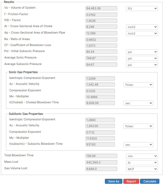
Results
- Vo – Volume of System (ft3)
- f – Friction Factor (in2)
- fl/D – Factor
- Ar – Cross-Sectional Area of Choke (in2)
- Ap – Cross-Sectional Area of Blowdown Pipe
- Ra – Ratio of Areas
- Cf – Coefficient of Blowdown Loss
- Psi – Initial Subsonic Pressure (psi)
- Average Sonic Pressure (psi)
- Average Subsonic Pressure (psi)
- Sonic Gas Properties
- Isentropic Compression Exponent
- Ac – Acoustic Velocity (ft/sec)
- Compression Exponent
- Mu – Multiplier
- t(Chocked) – Chocked Blowdown Time (sec)
- Subsonic Gas Properties
- Isentropic Compression Exponent
- Ac – Acoustic Velocity (ft/sec)
- Compression Exponent
- Mu – Multiplier
- t(Chocked) – Chocked Blowdown Time (sec)
- Total Blowdown Time (min)
- Mass Lost (lb)
- Gas Volume Lost (MCF)
References
- Pipeline Design for Hydrocarbons Gases and Liquids, Committee of pipeline planning, American Association of Civil Engineers, 1975
- Engineering Data Book, Volume II, Gas Processor Association, Revised Tenth Edition, 1994
- Pipeline Design & Construction, A Practical Approach, American Society of Mechanical Engineers, 2000
FAQ
-
Gas Purging Calculations?
Purging is a process of removing gas from the pipeline. Controlled purging of gases from pipelines by direct displacement with other gases that have been safely practiced for many years with the recognition that some flammable mixture is present. Purging of gases from pipelines by direct displacement with another gas also has been similarly practiced. It works both ways; however, there will always be an atmosphere of type of a mixture. This is due to the densities of the gases. Check Out
-
What are the differences between the Semiempirical Blowdown calculation and the AGA Blowdown calculation?
AGA blowdown calculation is based on the specification defined by American Gas Association. Semiempirical blowdown calculation was developed from the SW Research Report calculations for the blowdown time and mass of gas vented to atmosphere of a piping system. Check Out