
Introduction
The PLTB User’s Guide presents information, guidelines, and procedures for use during design, construction, operations, and integrity tasks for field or office applications. Horizontal Directional Drilling (HDD) is for professionals involved in the design, engineering, and installation of pipelines and utilities by horizontal directional drilling.
The HDD module provides a means to generate high-level drill designs and/or check and analyze existing designs you may encounter in the field. The underlying mathematical models and technical procedures are based on the latest HDD technology and are following current regulations, standards, and recommended practices. The HDD module provides standard stress and pull force analysis for steel, drilling fluid, and pressure analysis, and addresses the installation of cables in conduits.
Installation of Cables in Conduits and Pipes
When pipes are installed by HDD, they often experience high tension loads, severe bending, and external fluid pressures. Often these installation loads are more severe than the design service loads. When selecting the appropriate pipe materials for an HDD installation, the designer must consider the pipe properties as well as the borehole profile. These two factors should be considered together in order to choose the best material and profile so that the pipeline can be installed and operated without risk of damage. To ensure that the material and bore-hole profile are suitable for the proposed application, the installation, operational, and combined loads and stresses are analyzed.
Cables installed into conduits have installation parameters such as maximum pulling tensions, sidewall pressure, clearance, and jamming, which must be considered. Cable damaged during installation can cause service failures. Mechanical stresses during installation are generally more severe than those encountered while in service.
Cable Jamming
J=\frac{D}{d}
J=\frac{D}{d}J = Jam Ratio
D = Inside Diameter of the Duct
d = Nominal Outside Diameter of One Cable (inch)
If 2.8 <= J<=3.0 jamming could occur, and it’s not recommended that the cable is pulled with this jam ratio
Clearance
Clearance is the distance between the top of the uppermost cable in the conduit and
the inner top surface of the conduit. It should be at least 10% of the conduit inner
diameter or one inch for large cables or installations involving numerous bends.
Equations for calculating clearance (CL) are presented as follows:
a) Single Cable Pull
C=D-d’\~\d’=1.05 \,d
C=D-d'\\~\\d'=1.05 \,d
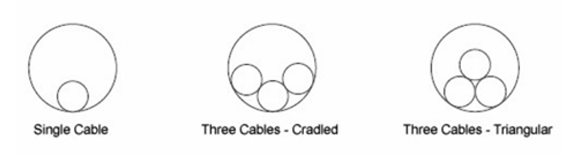
b) There Cable Pull (Cradle Configuration)
C = \frac{D}{2} + \frac{d’}{2} + \frac{(D-d’)}{2} \sqrt{1 – \left(\frac{d’}{2(D-d)}\right)^2}
C = \frac{D}{2} + \frac{d'}{2} + \frac{(D-d')}{2} \sqrt{1 - \left(\frac{d'}{2(D-d)}\right)^2}
c) Three Cable Pull (Triangular Configuration)
C = \frac{D}{2} – 1.366d’ + 0.5(D – d’) \left( 1 – \left( \frac{d’}{D – d’} \right)^2 \right)^{0.5}
C = \frac{D}{2} - 1.366d' + 0.5(D - d') \left( 1 - \left( \frac{d'}{D - d'} \right)^2 \right)^{0.5}
Weight Correction Factor
The configuration of cables can affect cable tension. A weight correction factor (Wc) is
used in the tension equations to account for this effect. The value for the weight correction factor is determined from the equations that follow:
a) Three Single Cables in Cradle Configuration
Wc = 1 + \frac{4}{3} \left( \frac{d}{D – d} \right)^2
Wc = 1 + \frac{4}{3} \left( \frac{d}{D - d} \right)^2
b) There Single Cables in Triangular Configuration
Wc = \frac{1}{\sqrt{1 – \left( \frac{d}{D – d} \right)^2}}
Wc = \frac{1}{\sqrt{1 - \left( \frac{d}{D - d} \right)^2}}
c) Single Cable in Conduit
Wc=1 \~\Wc= \text{Weight Correction Factor}
Wc=1 \\~\\Wc= \text{Weight Correction Factor}Cable Pull Tension Calculator
Tension at Point “B”
T_B=T_A+L_{AB}W_c(\sin \alpha -KW_C \cos \alpha)
T_B=T_A+L_{AB}W_c(\sin \alpha -KW_C \cos \alpha)𝑇𝐵 – Tension at point “B” (lbf)
𝐿𝐴𝐵 – Measure length of section “A-B” (ft)
a – Conduit pipe entry angle (ᵒ)
K – Dynamic coefficient of friction
Tension at Point “C”
\theta_1 = \frac{L_{BC}}{R_1}\~\ K = K W_C\~\ T_C = T_B e^{K\theta_1} – \frac{W R_1}{(1 + K^2)} \left(2Ke^{K\theta_1}\sin{\theta_1} + (1 + K^2)(1 – e^{K\theta_1}\cos{\theta_1})\right)
\theta_1 = \frac{L_{BC}}{R_1}\\~\\ K = K W_C\\~\\ T_C = T_B e^{K\theta_1} - \frac{W R_1}{(1 + K^2)} \left(2Ke^{K\theta_1}\sin{\theta_1} + (1 + K^2)(1 - e^{K\theta_1}\cos{\theta_1})\right)
TC – Tension at point “C” (lbf)
θ1 – Angle measure from the vertical axis
LBC – Measure length of the curved section “B-C” (ft)
R1 – Radius of curvature (ft)
Tension at Point “D”
T_D=T_C+W_CKL_{CD}
T_D=T_C+W_CKL_{CD}𝑇𝐷 – Tension at point “D” (lbf)
𝐿𝐶𝐷 – Measure length for section “C-D”
Tension at Point “E”
\theta_2 = \frac{L_{DE}}{R_2}\~\K = K W_C\~\T_E = T_D e^{k\theta_2} – \frac{W R_2}{(1 + K^2)} \left(2K\sin{\theta_2} + (1 + K^2)(e^{k\theta_2} – \cos{\theta_2})\right)
\theta_2 = \frac{L_{DE}}{R_2}\\~\\K = K W_C\\~\\T_E = T_D e^{k\theta_2} - \frac{W R_2}{(1 + K^2)} \left(2K\sin{\theta_2} + (1 + K^2)(e^{k\theta_2} - \cos{\theta_2})\right)
TE – Tension at point “E” (lbf)
θ2 – Angle measure from the vertical axis
LDE – Measure length of the curved section “B-C” (ft)
R2 – Radius of curvature (ft)
Tension at Point “F”
T_F = T_E + L_{EF}W(\sin{\beta} + KW_C \cos{\beta})
T_F = T_E + L_{EF}W(\sin{\beta} + KW_C \cos{\beta})
TF – Tension at point “F” (lbf)
LEF – Measure length of section “A-B” (ft)
β – Conduit pipe exit angle (ᵒ)
Sidewall Pressure
Sidewall Pressure (SP) is exerted on a cable as it is pulled around a bend. Excessive sidewall pressure can cause cable damage and is the most restrictive factor in many installations
a) Single Cable in Conduits
\text{SWBP} = \frac{T2}{R}
\text{SWBP} = \frac{T2}{R}
b) Three Cable in Conduit – Cradle Configuration
\text{SWBP} = \frac{T2}{3R} (3W_C – 2)
\text{SWBP} = \frac{T2}{3R} (3W_C - 2)
c) Three Cable in Conduit – Triangular Configuration
\text{SWBP} = \frac{T2}{2R} W_C
\text{SWBP} = \frac{T2}{2R} W_C
T2 = Tension at Bend Exit
Input Parameters
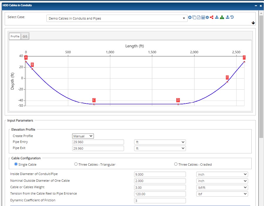
Cable Configuration
- Single Cable
- Three Cable – Triangular
- Three Cables – Cradled
Input Variable: Pipe, Cable, and Friction
- Inside Diameter of Conduit/Pipe (inch)
- Nominal Outside Diameter of One Cable (inch)
- Cable or Cables Weight (inch)
- Tension from the Cable Reel to Pipe Entrance (inch)
- Dynamic Coefficient of Friction (dimensionless)
- Create Profile (Shape, Excel, Manual)
- Pipe Entry (ft)
- Pipe Exit (ft)
Input Variable: Pipe Pulling Profile*:
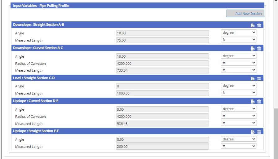
- Downslope: Straight Section A – B
- Pipe Entry Angle A – B [degree]
- Measured Length A – B [ft]
- Downslope: Curved Section B – C
- Bend Angle B – C [degree]
- Radius of Curvature B – C [ft]
- Straight Section C – D
- Horizontal Angle[degree]
- Measured Length [ft]
- Upslope: Curved Section D – E
- Bend Angle D – E [degree]
- Radius of Curvature [ft]
- Upslope: Straight Section E – F
- Pipe Exit Angle E – F [degree]
- Measured Length E – F [ft]
*The input entry varies depending on the number of sections added.
Outputs/Reports
- View the results.
- To SAVE, be sure to fill out all project details then click the SAVE button.
- To generate a REPORT, click the REPORT button.
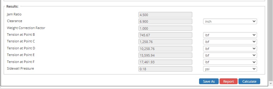
- Jam Ratio (dimensionless)
- Clearance (inch)
- Weight Correction Factor (dimensionless)
- Tension at Point B (lbf)
- Tension at Point C (lbf)
- Tension at Point D (lbf)
- Tension at Point E (lbf)
- Tension at Point F (lbf)
- Tension at Point G (lbf)
- Sidewall Pressure (psi)
References
- Willoughby, David (2005). Horizontal Directional Drilling, McGraw-Hill, New York, ISBN 0-87814-395-5. v.
- Willoughby, David, Training – Horizontal Directional Drilling, TTI, November 2016
- HDD Consortium. (2001). Horizontal directional drilling, good practices guidelines, HDD Consortium.
- Horizontal Directional Drilling Training Manual, Horizontal Drilling International, February 1999
- Skonberg, Eric R. II. Muindi, Tennyson M. (2014). Pipeline Design for Installation by Horizontal Directional Drilling, American Society of Civil Engineers. Horizontal Directional Drilling Design Guideline Task Committee.
- “Installation of Pipelines by Horizontal Directional Drilling”, PRCI Report PR-227-9424
- Nayyar, Mohinder L. (1992). Piping Handbook, 6th Edition, McGraw-Hill, New York, NY.
- AWWA (2006), PE Pipe Design and Installation, M55, American Water Works Association, Denver, CO
- ASTM (1962), PPI Handbook
AUGER BORING – Casing is jacked into the ground as a rotating auger works simultaneously to remove the excavated soil. It is commonly used in applications where settlement is a concern: under highways, railways and levies. Also known as a dry bore.
BENTONITE – A natural clay material used as a basic ingredient for drilling muds and lubricants to facilitate ease of installation.
BORE OR BOREHOLE – drilling term – The elongated cavity created by the drilling process. Often the borehole is not a void, but rather a hole filled with drilling mud and cuttings. Well casing is pulled or pushed into the borehole to complete a well.
CASING – drilling term – The non-perforated or non-slotted pipe that comprises the entry and exit sections of a horizontal well, as opposed to the well screen. Surface casing is a pipe that is set through loose surficial deposits to stabilize the bore, so the deeper sections can be drilled without difficulty from caving or collapse in the upper section of the borehole.
CROSSING – A pipeline installation designed to pass beneath a surface obstruction. Examples of crossings include roads, railway tracks, water bodies, pipeline corridors, and utilities.
DRILLING MUD – drilling material – aqueous slurry that is used during drilling to transport drill cuttings from the borehole, prevent borehole collapse and provide lubrication for the drill string. Most horizontal drilling uses drilling mud of some sort, although in some conditions it is possible or preferable to drill using air or water. Drilling mud made be made using the mineral bentonite, synthetic or natural polymers, or some combination of the two.
DRILL RIG – A trenchless machine that installs pipes and cables by drilling a pilot hole that can be enlarged (if necessary), and then pulling the product line.
ENTRY POINT – The starting location of the crossing where the drill enters the ground.
EXIT POINT – The end location of the crossing.
FORWARD REAMER – drilling tool – A type of reamer used to enlarge the diameter of the borehole in a blind or single-entry well.
HORIZONTAL DIRECTIONAL DRILLING (HDD) – A surface-based trenchless technology that involves a horizontal bore under the surface along a planned pathway. Once the HDD creates a bore of a suitable size – which may require one or multiple passes by the drilling apparatus – the conduit or pipe is pulled into the bore and connections are made to the appropriate utilities.
OPEN CUT – Underground construction method involving excavation from ground level to the level required for the installation, maintenance, or inspection of a pipe, conduit, or cable. Upon completion of the work, the trench is backfilled, and the surface restored. Backhoe excavation is an example of open-cut construction.
PILOT BORE – drilling term – The initial boring made in a horizontal well installation. The pilot bore is steered, using any of several technologies, from a designated entry point, along a predetermined bore path, to a designated endpoint, either at the ground surface or at depth. The pilot bore subsequently may be reamed to a larger diameter to accommodate the desired size well screen and casing.
PIPE PULLING – Method used to replace small diameter pipes by attaching new product pipe to the existing pipe, which is then pulled out of the ground.
POTHOLE – drilling term – a small hole excavated from the surface to a buried utility in order to provide positive verification of its location.
REAMER – drilling tool – a cutting tool used to enlarge the diameter of a borehole after the pilot bore has been drilled.
FAQ
-
HDD Power Tool?
Horizontal Directional Drilling or HDD, is a method of installing steel or polyethylene pipe, conduit, or cables in a designed bore path, by using a drilling rig, with a minimal footprint to the environment. HDD process represents a significant improvement over traditional open cut and disturbance methods for installing pipelines beneath obstructions, such as rivers or roads, which require specialized construction attention. To take full advantage of the benefits offered by horizontal directional drilling and produce designs which can be efficiently executed in the field, design engineers need a working knowledge of the process with the appropriate HDD software. Check Out
-
HDD – Version Capability Matrix
Calculations and functions involving the capabilities that HDD can provide. Check Out
-
HDDPT Process to Import KML/KMZ and Shape Files?
Here relies the step-by-step procedure of importing files and having them project accurate calculations to your reports. Check Out
-
How to Calculate a Compound Angle?
The HDD PowerTool program will calculate the compound data based on the horizontal and vertical data you enter.
For example: In the below screenshot, under curve, select the compound. You may then input 2 data elements for the horizontal and vertical part of the bend. The program will then calculate the compound. Check Out
-
Update on the Latest Technical Capabilities of the HDDPT?
Steel cased crossings have been used to avoid load considerations, unstable soil conditions, third party mechanical damage or when conditions dictated by regulatory or sound engineering practices. However, due to a variety of factors such design, installation, construction practices, materials, coatings, etc. have caused problems with protecting the carrier pipe within the casing. Check Out
-
Combined Stresses and Limitations for Both Liquid & Gas HDD?
HDD combined stresses can be analyzed by calculating the maximum shear stress on a small element in the pipeline. Maximum shear stress should be limited to 45% of the SMYS of the pipe (ASME/ANSI B31.4). This is in accordance to PRCI report PR-227-9424 from the findings and conclusions of those companies who performed and approved the research work, However, the question comes up from time to time that the B31.4 code can be converted to B31.8’s code application. Check Out
-
Hydraulic Fracture Analysis Geological Layers Data Input?
Some typical values of soil friction angle are given below for different USCS soil types at normally consolidated condition unless otherwise stated. These values should be used only as guideline for geotechnical problems; however, specific condition of each engineering problem often needs to be considered for an appropriate choice of geotechnical parameters. Check Out