
Introduction
API 1117 Movement of In-Service Pipelines using the free span between pipe supports. PLTB predicts stresses due to pipe movement of in-service and out of service lines as well as operating pipelines having unintended free spans.
This calculation is based on a four-span loaded beam. Because there are many variables during the construction movement of the pipe to the new lowered bedding position, this puts limits on the stresses that can be calculated.
Step 1. Variable Definition
Where:
𝐷 − Pipe Outside Diameter (in)
𝑊 − Weight (lb/ft), includes water weight if hydrostatic testing is specified
MAOP − Maximum Allowable Operating Pressure (psi)
MOP – Maximum Operating Pressure [psi],
SMYS − Specified Minimum Yield Strength or Grade of Steel (psi)
OP − Operating Pressure (psi)
𝑡 − Pipe Wall Thickness (in)
𝑆 − Section Modulus (in3)
𝐼 − Moment of Inertia (in4)
𝑒 − Modulus of Elasticity (29000 ksi)
𝐻 − Hoop Stress (psi)
𝐵 − Bending Stress (psi)
𝑀 − Bending Moment (ft−lb)
𝐿 − Span Length (ft)
𝑑 − Deflection (in)
MAOP=\frac{2St}{D}FET
MAOP=\frac{2*SMYS*t}{D}F.E.T𝐹 − Design Factor
𝐸 − Longitudinal Joint Factor
𝑇 − Temperature Derating Factor
Step 2: Calculate Hoop Stress
H=\frac{PD}{2t}
H=\frac{PD}{2t}Where:
𝑃 = MOP
Step 3: Calculate Maximum Allowable Bending Stress
Solve Von Mises Equation through Quadratic Equation, and than solve for
Bending Stress B
B=\frac{-H^2-4H^2-(SF)^2}{2}
Von Mises Stress = percentSMYS = \sqrt{(H^2+HB+B^2)}B^2 +BH+H^2+(percentSMYS)^2 = 0
Step 4: Calculate Maximum Allowable Bending Moment
I=\frac{\pi}{4}(\frac{D}{2})^2-(\frac{D}{2t})^4\~\ B=\frac{M_c}{I},\,where\,S=\frac{I}{c},\,therefore\,B=\frac{M}{S},\,and\,M=BS
I=\frac{\pi}{4}(\frac{D}{2})^2-(\frac{D}{2t})^4\\~\\ B=\frac{M_c}{I},\,where\,S=\frac{I}{c},\,therefore\,B=\frac{M}{S},\,and\,M=BSStep 5: Calculate Maximum Span Length L, Due to Bending
M=\frac{WL^2}{8}\~\L=\sqrt{\frac{8M}{W}}
M=\frac{WL^2}{8}\\~\\L=\sqrt{\frac{8M}{W}}Step 6: Calculate Maximum Span Length L, Due to Deflection
d=\frac{5WL^4}{384EI},\,Maximum \,deflection\, must\, be \~\ d<\frac{L}{360}
d=\frac{5WL^4}{384EI},\,\\~\\Maximum \,deflection\, must\, be \ d<\frac{L}{360}Case Guide
Part 1: Create Case
- Select the Maximum Allowable Pipe Span Length application from the Design & Stress Analysis Module
- To create a new case, click the “Add Case” button
- Enter Case Name, Location, Date and any necessary notes.
- Fill out all required Parameters.
- Make sure the values you are inputting are in the correct units.
- Click the CALCULATE button to overview results.
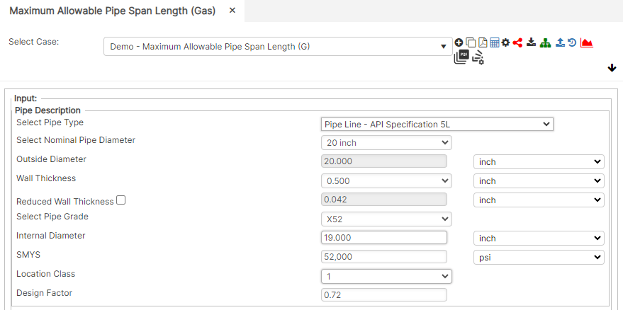
Input Parameters
- Nominal Pipe Size
- Outside Diameter (in)
- Wall Thickness (in.)
- Pipe Grade
- Internal Diameter (in)
- SMYS (psi)
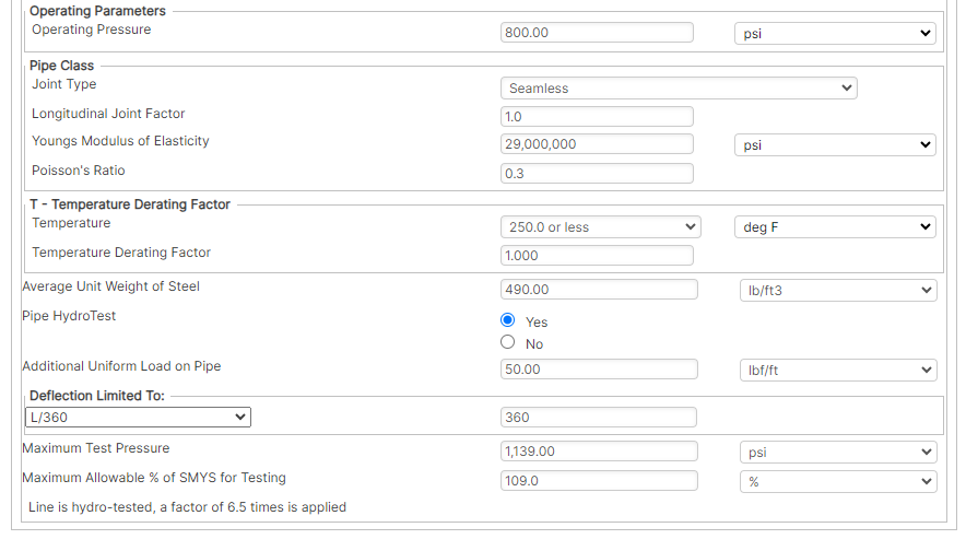
- Pipe Class
- Operating Pressure (psi)
- Joint Type (Dropdown)
- Longitudinal Joint Factor
- Youngs Modulus of Steel (psi)
- Poisson’s Ratio for Steel
- Temperature (°F)
- Temperature Derating Factor
- Average Unit Weight of Steel (Calculated)
- Pipe installed after November 11, 1970 (Y/N)
- Additional Uniform Load on Pipe
- Maximum Test Pressure (psi)
- Maximum Allowable % of SMYS for Testing (%)
Part 2: Outputs/Reports
- If you need to modify an input parameter, click the CALCULATE button after the change.
- To SAVE, fill out all required case details then click the SAVE button.
- To rename an existing file, click the SAVE As button. Provide all case info then click SAVE.
- To generate a REPORT, click the REPORT button.
- The user may export the Case/Report by clicking the Export to Excel icon.
- To delete a case, click the DELETE icon near the top of the widget.
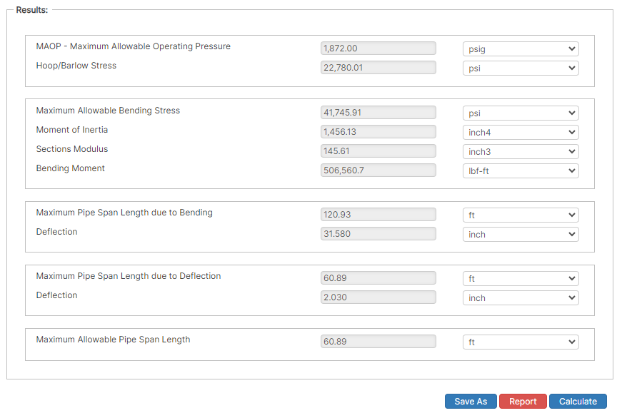
Results
- MAOP – Maximum Allowable Operating Pressure (psig)
- Hoop/Barlow Stress (psi)
- Maximum Allowable Bending Stress (psi)
- Moment of Inertia (in4)
- Sections Modulus (in3)
- Bending Moment (lbf-ft)
- Maximum Pipe Span Length due to Bending (ft)
- Deflection (in)
- Maximum Pipe Span Length due to Deflection (ft)
- Maximum Allowable Pipe Span Length (ft)
References
- ASME B31.8 – Gas Transmission and Distribution Piping Systems
- API 5L, API 5LS and API 5LX – Specification of Pipe Grade
- ASTM – Various – Weld Joint Factor
- CFR Code Part 192
- USDA-SCS Modified (Permissible Velocity of Water and Soil Erodibility)
- FHWA-HEC
- Pipeline Rules of Thumb Handbook
- Timoshenko, S – Theory of Elasticity Anchor Force
FAQ
-
Restrained versus Unrestrained Pipe (Difference in Gas vs. Liquid)?
ASME B31.4 liquid and B31.8 gas codes include calculations for the net longitudinal compressive stress that must be applied only for a restrained line that equates to a low (less than 2%) longitudinal strain. This stress status is characteristic to underground pipelines located some distance away from above ground piping facilities.
Unrestrained lines means those above ground sections of piping without axial restraint as with buried pipe with soil. In others words the soil exerts substantial axial restraint, but not fully restrained. Check Out
-
What is the Maximum Span Length of rev1?
Regarding span factors with and without water are based on bending stress and deflection. Larger diameter pipe spans require saddles for stability. Many standards that require pipes to be filled with water are based on bending and shear stresses not to exceed 1,500 psi and a deflection between supports not exceed 0.1 inches. Check Out
-
What is the model used for Thrust at Blow-Off?