
Introduction
The focal point of this application is to assess strain due to a falling object such as a piece of construction equipment, material or vehicle falls over an operating pipeline.
Some of the limitations of this calculation are as follows: drop height, maximum load at the soil surface, type of soil, etc. to determine the penetration depth.
Maximum Impact Load:
L_{max}=\sqrt{\frac{32WH_fGr_o}{\pi^2 (1-v)} }[lbs]
L_{max}=\sqrt{\frac{32WH_fGr_o}{\pi^2 (1-v)} }[lbs]Where:
𝐿𝑚𝑎𝑥 − Maximum Load at Soil Surface (lbs)
𝑊 − Weight of Falling Object (lbs)
𝐻𝑓 − Drop Height (in)
𝑟𝑜 − Least Horizontal Radius of Falling Object (in)
𝐺 − Soil Shear Modulus (psi)
𝑣 − Poisson’s Ratio for Soil (dimensionless)
For large strains, near the region of impact, the shear modulus is one tenth the low amplitude shear modulus. : G=\frac{\rho V_s^2}{10}
G=\frac{\rho V_s^2}{10}Where:
𝑉𝑠 − Shear Wave Velocity of Near Surface Soils (in/sec)
𝜌 − Mass Density of Near Surface Soil (Unit Weight of Soil/ Acceleration/ due to Gravity)(lb.sec2/in4)
Penetration Depth:
x_p=kP_a\log(1+\frac{V^2}{215000})[ft]
x_p=kP_a\log(1+\frac{V^2}{215000})[ft]Where:
𝑥𝑝 − Penetration Depth (ft)
𝑃𝑎 − Weight per Unit Impact Area (lb/ft2)
𝑉 − Impact Velocity (equal to (√2𝑔𝐻𝑓 )(ft/sec)
𝑘 − Empirical Coefficient of Penetration
(𝑘 = 0.0367 for Sandy Soil, k = 0.0482 for Soil with Vegetation, k = 0.0732 for Soft Soil)
Case Guide
Part 1: Create Case
- Select the Maximum Impact Load & Penetration Depth application from the Design & Stress Analysis Module
- To create a new case, click the “Add Case” button
- Enter Case Name, Location, Date and any necessary notes.
- Fill out all required Parameters.
- Make sure the values you are inputting are in the correct units.
- Click the CALCULATE button to overview results.
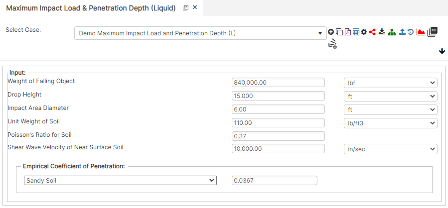
Input Parameters
- Weight of Falling Object (lbs)
- Drop Height (ft)
- Impact Area Diameter (ft)
- Unit Weight of Soil: (70-150) (lbs/ft³)
- Poisson’s Ratio for Soil
- Shear Wave Velocity of Near Surface Soil (in/sec)
- Empirical Coefficient of Penetration
Part 2: Outputs/Reports
- If you need to modify an input parameter, click the CALCULATE button after the change.
- To SAVE, fill out all required case details then click the SAVE button.
- To rename an existing file, click the SAVE As button. Provide all case info then click SAVE.
- To generate a REPORT, click the REPORT button.
- The user may export the Case/Report by clicking the Export to Excel icon.
- To delete a case, click the DELETE icon near the top of the widget.
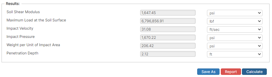
Results
- Soil Shear Modulus (psi)
- Maximum Load at the Soil Surface (lbf)
- Impact Velocity (ft/sec)
- Impact Pressure (psi)
- Weight per Unit of Impact Area (psi)
- Penetration Depth (ft)
References
- ASME B31.8 – Gas Transmission and Distribution Piping Systems
- API 5L, API 5LS and API 5LX – Specification of Pipe Grade
- ASTM – Various – Weld Joint Factor
- CFR Code Part 192
- MMS Regulations
- USDA-SCS Modified (Permissible Velocity of Water and Soil Erodibility)
- FHWA-HEC
- Pipeline Rules of Thumb Handbook
FAQ
-
Restrained versus Unrestrained Pipe (Difference in Gas vs. Liquid)?
ASME B31.4 liquid and B31.8 gas codes include calculations for the net longitudinal compressive stress that must be applied only for a restrained line that equates to a low (less than 2%) longitudinal strain. This stress status is characteristic to underground pipelines located some distance away from above ground piping facilities.
Unrestrained lines means those above ground sections of piping without axial restraint as with buried pipe with soil. In others words the soil exerts substantial axial restraint, but not fully restrained. Check Out
-
What is the Maximum Span Length of rev1?
Regarding span factors with and without water are based on bending stress and deflection. Larger diameter pipe spans require saddles for stability. Many standards that require pipes to be filled with water are based on bending and shear stresses not to exceed 1,500 psi and a deflection between supports not exceed 0.1 inches. Check Out
-
What is the model used for Thrust at Blow-Off?