
Introduction
A pipeline is subjected to three primary loading conditions during installation by HDD: tension, bending, and external pressure. A thorough design process requires examination of the stresses that result from each individual loading condition as well as an examination of the combined stresses that result from the interaction of these loads.
Hence, the stresses imposed on steel pipe during both the HDD installation process and subsequent operation should be carefully evaluated.
Bending Stress (fb)
Bending stress resulting from a rigid steel pipe
being forced to conform to the drilled radius of curvature
f_b=\frac{ED}{2R}
f_b=\frac{ED}{24*R}E =modulus of elasticity for steel (psi)
D = outside diameter of the pipe (inch)
R = Shortest Radius of Curvature (ft)
Hoop Stress (fh)
Steel pipe will fail by buckling or collapse when under the influence of hoop stress. It’s important to calculate the wall thickness required to prevent collapse of round steel pipe under the influence of hoop stress.
f_h = \frac{\Delta P D}{2t}\~\\Delta P = P – (H – H_w)0.4333
f_h = \frac{(P-\Delta P)D}{2t}\\~\\\Delta P = \frac{H * \rho_w} {12 * 12}
P = Operating Pressure (psi)
H = Depth of the Pipe (ft)
ρw= Weight of Water/ Mud (lb/ft^3)
Thermal Stress (fe)
Thermal stress resulting from changes in pipe temperature from the point in time at which the pipe is restrained by the surrounding soil to typical operating conditions.
f_e=E\alpha(T_2-T_1)
f_e=E\alpha(T_2-T_1)
𝐸 − Young′s Modulus of Elasticity 𝐸 = 29 x 106
𝛼 − Coefficient of Thermal Expansion for steel α = 6.5 x 10⁶ [in/in℉]
T1 = Installation Temperature (°F)
T2 = Operating Temperature (°F)
Total Longitudinal Compressive Stress
f_1=f_b+f_h\theta+f_e
f_l=-f_b+f_h*\nu+f_e
fl = Total Longitudinal Compressive Stress
ν = Poisson′s Ratio = 0.3
Maximum Shear Stress (fv)
f_v=\frac{f_h-f_1}{2}
f_v=\frac{f_h-f_l}{2}Maximum Allowable Shear Stress (fva)
f_{va}=0.45SMYS
f_{va}=0.45*SMYSSMYS – Specified minimum Yield Stress for Steel Pipe (psi)
Operating Conditions
\text{Operating Condition} =
\begin{cases}
\text{Pass: } f_{va} < f_v \ \text{Fail: } f_{va} > f_v
\end{cases}
\text{Operating Condition} =
\begin{cases}
\text{Pass: } f_{v} < f_{va} \\
\text{Fail: } f_{v} > f_{va}
\end{cases}
Input Parameters
- To create a new case, click the “Add Case” button
- Select the Operational Stresses – Steel Pipe application in the HDD Steel Pipe module
- Enter Case Name, Location, Date, and any necessary notes
- Fill out all required fields
- Make sure the values you are inputting are in the correct units
- Click the CALCULATE button
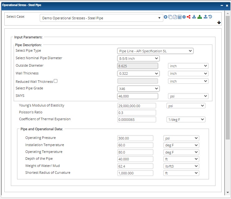
- Poisson’s Ratio
- Young’s Modulus of Elasticity [psi]
- Thermal Expansion Coefficient [in./in.°F]
- Operating Pressure [psig]
- Pipe Outside Diameter [in.]
- Pipe Wall Thickness [in.]
- Specified Minimum Yield Strength [psi]
- Installation Temperature [°F]
- Operating Temperature [°F]
- Depth of the Pipe at Horizontal Section [ft]
- Groundwater Table below Datum [ft]
- Shortest Radius of Curvature [ft]
Outputs/Reports
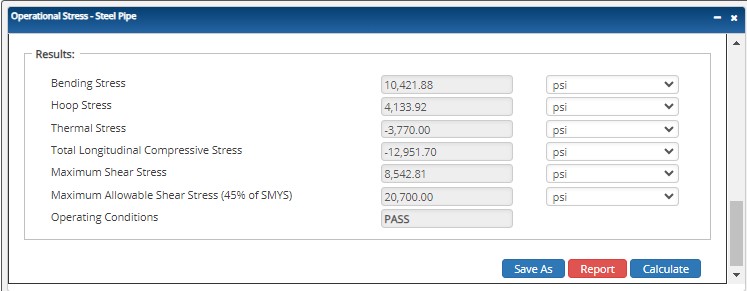
- View the results
- If an input parameter needs to be edited be sure to hit the CALCULATE button after the change
- To SAVE, fill out all required case details then click the SAVE button
- To rename an existing file, click the SAVE As button. Provide all case info then click SAVE
- To generate a REPORT, click the REPORT button
- The user may export the Case/Report by clicking the Export to Excel/PowerPoint icon
- To delete a case, click the DELETE icon near the top of the widget
- Bending Stress [psi]
- Hoop Stress [psi]
- Thermal Stress [psi]
- Total Longitudinal Compressive Stress [psi]
- Maximum Shear Stress [psi]
- Maximum Allowable Shear Stress (45% of SMYS)
- Operating Conditions
References
- Willoughby, David (2005). Horizontal Directional Drilling, McGraw-Hill, New York, ISBN 0-87814-395-5. v.
- Willoughby, David, Training – Horizontal Directional Drilling, TTI, November 2016
- HDD Consortium. (2001). Horizontal directional drilling, good practices guidelines, HDD Consortium.
- Horizontal Directional Drilling Training Manual, Horizontal Drilling International, February 1999
- Skonberg, Eric R. II. Muindi, Tennyson M. (2014). Pipeline Design for Installation by Horizontal Directional Drilling, American Society of Civil Engineers. Horizontal Directional Drilling Design Guideline Task Committee.
- “Installation of Pipelines by Horizontal Directional Drilling”, PRCI Report PR-227-9424
- Nayyar, Mohinder L. (1992). Piping Handbook, 6th Edition, McGraw-Hill, New York, NY.
- AWWA (2006), PE Pipe Design and Installation, M55, American Water Works Association, Denver, CO
- ASTM (1962), PPI Handbook
AUGER BORING – Casing is jacked into the ground as a rotating auger works simultaneously to remove the excavated soil. It is commonly used in applications where settlement is a concern: under highways, railways and levies. Also known as a dry bore.
BENTONITE – A natural clay material used as a basic ingredient for drilling muds and lubricants to facilitate ease of installation.
BORE OR BOREHOLE – drilling term – The elongated cavity created by the drilling process. Often the borehole is not a void, but rather a hole filled with drilling mud and cuttings. Well casing is pulled or pushed into the borehole to complete a well.
CASING – drilling term – The non-perforated or non-slotted pipe that comprises the entry and exit sections of a horizontal well, as opposed to the well screen. Surface casing is a pipe that is set through loose surficial deposits to stabilize the bore, so the deeper sections can be drilled without difficulty from caving or collapse in the upper section of the borehole.
CROSSING – A pipeline installation designed to pass beneath a surface obstruction. Examples of crossings include roads, railway tracks, water bodies, pipeline corridors, and utilities.
DRILLING MUD – drilling material – aqueous slurry that is used during drilling to transport drill cuttings from the borehole, prevent borehole collapse and provide lubrication for the drill string. Most horizontal drilling uses drilling mud of some sort, although in some conditions it is possible or preferable to drill using air or water. Drilling mud made be made using the mineral bentonite, synthetic or natural polymers, or some combination of the two.
DRILL RIG – A trenchless machine that installs pipes and cables by drilling a pilot hole that can be enlarged (if necessary), and then pulling the product line.
ENTRY POINT – The starting location of the crossing where the drill enters the ground.
EXIT POINT – The end location of the crossing.
FORWARD REAMER – drilling tool – A type of reamer used to enlarge the diameter of the borehole in a blind or single-entry well.
HORIZONTAL DIRECTIONAL DRILLING (HDD) – A surface-based trenchless technology that involves a horizontal bore under the surface along a planned pathway. Once the HDD creates a bore of a suitable size – which may require one or multiple passes by the drilling apparatus – the conduit or pipe is pulled into the bore and connections are made to the appropriate utilities.
OPEN CUT – Underground construction method involving excavation from ground level to the level required for the installation, maintenance, or inspection of a pipe, conduit, or cable. Upon completion of the work, the trench is backfilled, and the surface restored. Backhoe excavation is an example of open-cut construction.
PILOT BORE – drilling term – The initial boring made in a horizontal well installation. The pilot bore is steered, using any of several technologies, from a designated entry point, along a predetermined bore path, to a designated endpoint, either at the ground surface or at depth. The pilot bore subsequently may be reamed to a larger diameter to accommodate the desired size well screen and casing.
PIPE PULLING – Method used to replace small diameter pipes by attaching new product pipe to the existing pipe, which is then pulled out of the ground.
POTHOLE – drilling term – a small hole excavated from the surface to a buried utility in order to provide positive verification of its location.
REAMER – drilling tool – a cutting tool used to enlarge the diameter of a borehole after the pilot bore has been drilled.
FAQ
-
HDD Power Tool?
Horizontal Directional Drilling or HDD, is a method of installing steel or polyethylene pipe, conduit, or cables in a designed bore path, by using a drilling rig, with a minimal footprint to the environment. HDD process represents a significant improvement over traditional open cut and disturbance methods for installing pipelines beneath obstructions, such as rivers or roads, which require specialized construction attention. To take full advantage of the benefits offered by horizontal directional drilling and produce designs which can be efficiently executed in the field, design engineers need a working knowledge of the process with the appropriate HDD software. Check Out
-
HDD – Version Capability Matrix
Calculations and functions involving the capabilities that HDD can provide. Check Out
-
HDDPT Process to Import KML/KMZ and Shape Files?
Here relies the step-by-step procedure of importing files and having them project accurate calculations to your reports. Check Out
-
How to Calculate a Compound Angle?
The HDD PowerTool program will calculate the compound data based on the horizontal and vertical data you enter.
For example: In the below screenshot, under curve, select the compound. You may then input 2 data elements for the horizontal and vertical part of the bend. The program will then calculate the compound. Check Out
-
Update on the Latest Technical Capabilities of the HDDPT?
Steel cased crossings have been used to avoid load considerations, unstable soil conditions, third party mechanical damage or when conditions dictated by regulatory or sound engineering practices. However, due to a variety of factors such design, installation, construction practices, materials, coatings, etc. have caused problems with protecting the carrier pipe within the casing. Check Out
-
Combined Stresses and Limitations for Both Liquid & Gas HDD?
HDD combined stresses can be analyzed by calculating the maximum shear stress on a small element in the pipeline. Maximum shear stress should be limited to 45% of the SMYS of the pipe (ASME/ANSI B31.4). This is in accordance to PRCI report PR-227-9424 from the findings and conclusions of those companies who performed and approved the research work, However, the question comes up from time to time that the B31.4 code can be converted to B31.8’s code application. Check Out
-
Hydraulic Fracture Analysis Geological Layers Data Input?
Some typical values of soil friction angle are given below for different USCS soil types at normally consolidated condition unless otherwise stated. These values should be used only as guideline for geotechnical problems; however, specific condition of each engineering problem often needs to be considered for an appropriate choice of geotechnical parameters. Check Out