
Specific Radius of Curvature
This procedure is for designing the bore path specific using radius of curvature calculations for plastic pipe that are basically the same as discussed for steel pipe. As with steel product pipe, plastic pipe, when installed by HDD, may experience high-tension loads, severe bending, and external fluid pressures. HDD installation subjects the pipe to axial tensile forces caused by the frictional drag between the pipe and the borehole or drilling fluid, the frictional drag on the ground surface, the capstan effect around drill-path bends, and hydrokinetic drag. The pipe may also be subjected to external hoop pressures caused by the external fluid head and bending stresses. Determination of pullback forces involves the assumption of many variables and installation techniques that include:
Calculation Overview
Pipe Weight:
\text{Pipe}_{weight} = \pi \cdot D^2 \cdot \frac{DR – 1}{DR^2} \cdot \rho_w\gamma_a
\text{Pipe}_{weight} = \pi \cdot D^2 \cdot \frac{DR - 1}{DR^2} \cdot \rho_w\gamma_aPipe weight – Weight of the pipe (lbs/ft)
D – Pipe Outside Diameter (inch)
DR – Diameter Ratio (D/t)
𝜌𝑤 = Density of water (lb/ft3)
𝛾𝑎 = Specific gravity of pipe material
Pipe Exterior Volume:
\text{Pipe}_{ext.vol} = \left( \frac{D}{24} \right)^2 \cdot \pi
\text{Pipe}_{ext.vol} = \left( \frac{D}{24} \right)^2 \cdot \piPipe Interior Volume:
\text{Pipe}_{interior.vol} = \left( \frac{D – 2t}{24} \right)^2 \cdot \pi
\text{Pipe}_{interior.vol} = \left( \frac{D - 2t}{24} \right)^2 \cdot \piWeight of Water in pipe:
(to be calculated only if the pipe is filled with water)
Water_{{p \cdot weight}} = Pipe_{{interior \cdot vol}} \times W_{\text{weight}}
Water_{{p \cdot weight}} = Pipe_{{interior \cdot vol}} \times W_{\text{weight}}Wweight – Weight of water (lb/ft3)
Displaced Mud Weight:
Displacemud_{\text{weight}} = Pipe_{{ext \cdot vol}} \times mud_{wt}
Displacemud_{\text{weight}} = Pipe_{{ext \cdot vol}} \times mud_{wt}mudwt = Weight of mud (lb/ft3)
Effective Weight of Pipe:
W_a = 1.06 \cdot \text{Pipe}{weight}\~\ W_S = W_a + \text{Water}{p\cdot weight} – \text{Displacemud}_{weight}
W_a = 1.06 \cdot \text{Pipe}_{weight}\\~\\ W_S = W_a + \text{Water}_{p\cdot weight} - \text{Displacemud}_{weight}
Hydrokinetic Force:
T_{hk}=hydro_{pressure}\frac{\pi}{8}(D_{bh}^2-D^2)
T_{hk}=hydro_{pressure}\frac{\pi}{8}(D_{bh}^2-D^2)Thk = hydro kinetic force (lbs)
Dbh = Borehole diameter, usually 1.5.D (inch)
Straight section A-B
Tension on Section:
\Delta T_2 = | \text{fric}2 | + \text{Drag}_2 – W_s L_1 \sin \theta{s1}+T_{hk}
\Delta T_2 = μ mud *|W_s| L_1 \cos \theta_{s1}+T_{hk}Cumulative Pull Load:
T_2=\Delta T_2+T_1
T_2=\Delta T_2+T_1
T1 – Pull back as the pipe enters the drill hole (lbf)
Curved Section B-C
h3 = R_1 \left( 1 – \cos\left(\frac{\theta_{C1}}{2}\right) \right) \~\ I_3 = \pi (D – t)^3 \frac{t}{8} \ j_3 = \left( E\frac{ I_3}{T_{\text{avgassumed3}}} \right)^{\frac{1}{2}} \~\ U3 = \frac{L_{\text{arc1}}}{J_3} \~\ X3 = 3 \frac{L_{\text{arc1}}}{12} – \left( \frac{j_3}{2} \right) \tanh\left( \frac{U_3}{2} \right) \~\ Y3 = 18 \left( \frac{L_{\text{arc1}}}{12} \right)^2 – j_3^2 \left( 1 – \frac{1}{\cosh\left(\frac{U_3}{2}\right)} \right) \~\ N_3 = \frac{T_{\text{avgassumed3}} h_3 – W_s \cos\left(\frac{\theta_{C1}}{2}\right) Y_3}{X_3}
Tension on Section:
\Delta T_3 = 2|\text{fric}3| + \text{Drag}_3 – W_s L{\text{arc}1} \sin\left(\frac{\theta_{C1}}{2}\right) +T_{hk}
\Delta T_3 = e^{(μmud* {\theta_{C1}})} * (μmud*|W_s|* L_{\text{arc}1})
Cumulative Pull Load:
T_3=\Delta T_3+T_2
T_3=\Delta T_3+T_2
Straight Section C-D
Tension on Section:
\Delta T_4 = |\text{fric}4| + \text{Drag}_4 – W_s L_s \sin \theta_s+T{hk}
\Delta T_4 = μ mud *|W_s| L_2 \cos \theta_{s2}Cumulative Pull Load:
T_4 = \Delta T_4 + T_3
T_4 = \Delta T_4 + T_3
Curved Section D-E
h5 = R_2 \left( 1 – \cos\left(\frac{\theta_{C2}}{2}\right) \right) \~\ I_5 = \pi (D – t)^3 \frac{t}{8} \ j_5 = \left( E\frac{ I_5}{T_{\text{avgassumed5}}} \right)^{\frac{1}{2}} \~\ U_5 = \frac{L_{\text{arc2}}}{J_5} \~\ X_5 = 3 \frac{L_{\text{arc2}}}{12} – \left( \frac{j_5}{2} \right) \tanh\left( \frac{U_5}{2} \right) \~\ Y_5 = 18 \left( \frac{L_{\text{arc2}}}{12} \right)^2 – j_5^2 \left( 1 – \frac{1}{\cosh\left(\frac{U_5}{2}\right)} \right) \~\ N_5 = \frac{T_{\text{avgassumed5}} h_5 – W_s \cos\left(\frac{\theta_{C2}}{2}\right) Y_5}{X_5}
Tension on Section:
\Delta T_5 = 2|\text{fric}5| + \text{Drag}_5 – W_s L{\text{arc2}} \sin\left(\frac{\theta_{C2}}{2}\right)+T_{hk}
\Delta T_5 = e^{(μmud* {\theta_{C2}})} * (μmud*|W_s|* L_{\text{arc}2})
Cumulative Pull Load:
T_5=\Delta T_5+T_4
T_5=\Delta T_5+T_4
Straight Section E-F
Tension on Section:
\Delta T_6 = |\text{fric}6| + \text{Drag}_6 – W_s L_1 \sin\theta{s1}
\Delta T_6 = μ mud *|W_s| L_3 \cos \theta_{s3}θS3 – Angle in degrees from horizontal for straight section
Cumulative Pull Load:
T_6=\Delta T_6+T_5
T_6=\Delta T_6+T_5
Total pull load of the pipe:
T_{total}=\Delta T_2+\Delta T_3+\Delta T_4+\Delta T_5+\Delta T_6
T_{total}=\Delta T_2+\Delta T_3+\Delta T_4+\Delta T_5+\Delta T_6Ttotal – Total pull load of the pipe (lbf)
Bending Strain:
R = 40D\~\ \varepsilon_{\text{ain}} = \frac{D}{2.R_1}\~\ \varepsilon_{\text{aex}} = \frac{D}{2.R_2}
R = 40D\\~\\ \varepsilon_{\text{ain}} = \frac{D}{2.R_1}\\~\\ \varepsilon_{\text{aex}} = \frac{D}{2.R_2}
Bending Stress:
\delta_{\text{ain}} = E_{24} \cdot \varepsilon_{\text{ain}}\~\\delta_{\text{aex}} = E_{24} \cdot \varepsilon_{\text{aex}}
\delta_{\text{ain}} = E_{short} \cdot \varepsilon_{\text{ain}}\\~\\\delta_{\text{aex}} = E_{short} \cdot \varepsilon_{\text{aex}}
Eshort = Pullback Modulus of Elasticity (typically short-term or 10 hr)
Allowable Tensile Stress:
\delta_{\text{allow}} = \delta_{\text{sp}} – \frac{E_{24} \cdot D}{2 \cdot R_2}
\delta_{\text{allow}} = \delta_{\text{sp}} - \frac{E_{short} \cdot D}{2 \cdot R_2}δsp – Allowable/Safe Pull Stress (psi)
Tensile Stress at Point A:
\sigma_1 = \frac{T_1}{\pi \cdot D^2} \left( \frac{D R^2}{D R – 1} \right)\~\\frac{\text{PASS}}{\text{FAIL}} =\begin{cases} \text{PASS if } \sigma_1 < \delta_{\text{allow}} \\text{Fail if } \sigma_1 > \delta_{\text{allow}}\end{cases}
\sigma_1 = \frac{T_1}{\pi \cdot D^2} \left( \frac{D R^2}{D R - 1} \right)\\~\\\frac{\text{PASS}}{\text{FAIL}} =\begin{cases} \text{PASS if } \sigma_1 < \delta_{\text{allow}} \\\text{Fail if } \sigma_1 > \delta_{\text{allow}}\end{cases}Tensile Stress at Point B:
\sigma_2 = \frac{T_2}{\pi \cdot D^2} \left( \frac{D R^2}{D R – 1} \right)
\sigma_2 = \frac{T_2}{\pi \cdot D^2} \left( \frac{D R^2}{D R - 1} \right)Tensile Stress at Point C:
\sigma_3 = \frac{T_3}{\pi \cdot D^2} \left( \frac{D R^2}{D R – 1} \right) + \frac{E_{24} \cdot D}{2 \cdot R_1} + \delta_{\text{ain}}
\sigma_3 = \frac{T_3}{\pi \cdot D^2} \left( \frac{D R^2}{D R - 1} \right) + \frac{E_{short} \cdot D}{2 \cdot R_1} + \delta_{\text{ain}}Tensile Stress at Point D:
\sigma_4 = \frac{T_4}{\pi \cdot D^2} \left( \frac{D R^2}{D R – 1} \right)
\sigma_4 = \frac{T_4}{\pi \cdot D^2} \left( \frac{D R^2}{D R - 1} \right)Tensile Stress at Point E:
\sigma_5 = \frac{T_5}{\pi \cdot D^2} \left( \frac{D R^2}{D R – 1} \right) + \frac{E_{24} \cdot D}{2 \cdot R_2} + \delta_{\text{aex}}
\sigma_5 = \frac{T_5}{\pi \cdot D^2} \left( \frac{D R^2}{D R - 1} \right) + \frac{E_{short} \cdot D}{2 \cdot R_2} + \delta_{\text{aex}}Tensile Stress at Point F:
\sigma_6 = \frac{T_6}{\pi \cdot D^2} \left( \frac{D R^2}{D R – 1} \right)
\sigma_6 = \frac{T_6}{\pi \cdot D^2} \left( \frac{D R^2}{D R - 1} \right)Breakaway Links Settings:
F_b = \delta_{sp} \cdot \frac{\pi}{4} \cdot (D^2 – ID^2)\~\\text{Result}{\text{pull}} = \begin{cases} \text{PASS} \,\, \text{if } \text{Total}{\text{pull}} < F_b \ \text{FAIL} \,\, \text{if } \text{Total}_{\text{pull}} > F_b\end{cases}
F_b = \delta_{sp} \cdot \frac{\pi}{4} \cdot (D^2 - ID^2)\\~\\\text{Result}_{\text{pull}} = \begin{cases} \text{PASS} \,\, \text{if } \text{Total}_{\text{pull}} < F_b \\ \text{FAIL} \,\, \text{if } \text{Total}_{\text{pull}} > F_b\end{cases}Static Head Pressure:
P_{\text{ext}} = \rho_w \cdot \gamma_b \cdot H
P_{\text{ext}} = \rho_w \cdot \gamma_b \cdot HH = depth of the bore profile (ft), usually the depth of the horizontal section
γb – Specific Gravity of the mud slurry
𝜌𝑤 = Density of water (lb/ft3)
Maximum Pressure During Pull back
P_{\text{max}} = P_{\text{ext}} + \text{hydro}_{\text{pressure}}
P_{\text{max}} = P_{\text{ext}} + \text{hydro}_{\text{pressure}}Ovality Compensation Factor:
\%\Delta D = \frac{0.0125 \cdot P_{\text{max}}}{\frac{E_{\text{long}}} {12(DR – 1)^3}} \cdot 100
\%\Delta D = \frac{0.0125 \cdot P_{\text{max}}}{\frac{E_{\text{short}}} {12(DR - 1)^3}} \cdot 100Buoyant Deformation:
\% \Delta D_b = \frac{0.088 \cdot \text{mud}{wt} \cdot D \cdot (DR – 1)^4}{E{\text{long}} \cdot DR} \cdot 100
\% \Delta D_b = \frac{0.088 \cdot \text{mud}_{wt} \cdot D \cdot (DR - 1)^4}{E_{\text{short}} \cdot DR} \cdot 100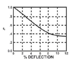
f0 – Ovality compensation factor based on % of Deflection (%Δ𝐷,%Δ𝐷𝑏)
Tensile Reduction Factor:
r = \frac{\sigma_4}{2 \cdot \delta_{\text{allow}}}\~\ f_r = \left(\sqrt{(5.57 – (r + 1.09))^2}\right) – 1.09
r = \frac{\sigma_4}{2 \cdot \delta_{\text{allow}}}\\~\\ f_r = \left(\sqrt{(5.57 - (r + 1.09))^2}\right) - 1.09Critical Collapse Pressure:
Pcr = \frac{2E_{24}}{1 – \mu^2} \cdot \left( \frac{1}{DR – 1} \right)^3 \cdot f_o \cdot f_r
Pcr = \frac{2E_{short}}{1 - \mu^2} \cdot \left( \frac{1}{DR - 1} \right)^3 \cdot f_o \cdot f_rSafety Factor:
SF = \frac{P_{cr}}{P_{\text{max}}}
SF = \frac{P_{cr}}{P_{\text{max}}}Input Parameters
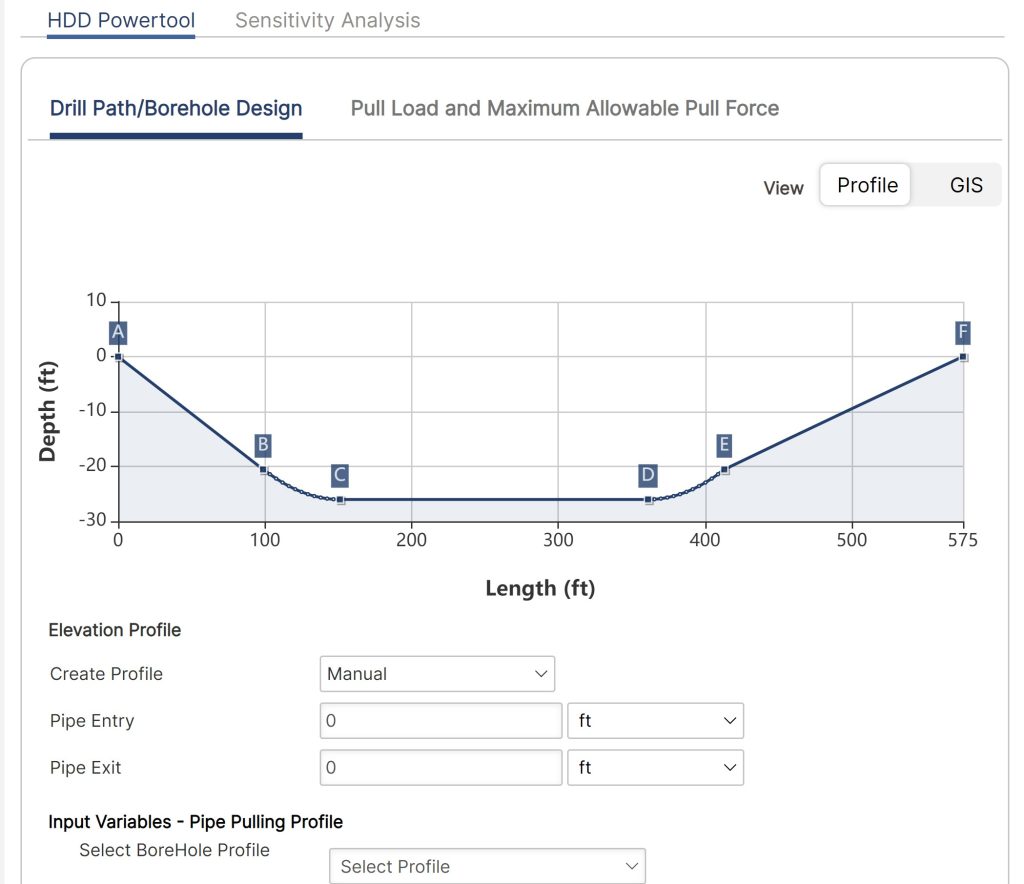
Elevation Profile:
- Create Profile
- Pipe Entry
- Pipe Exit
Drill Path/Borehole Design:
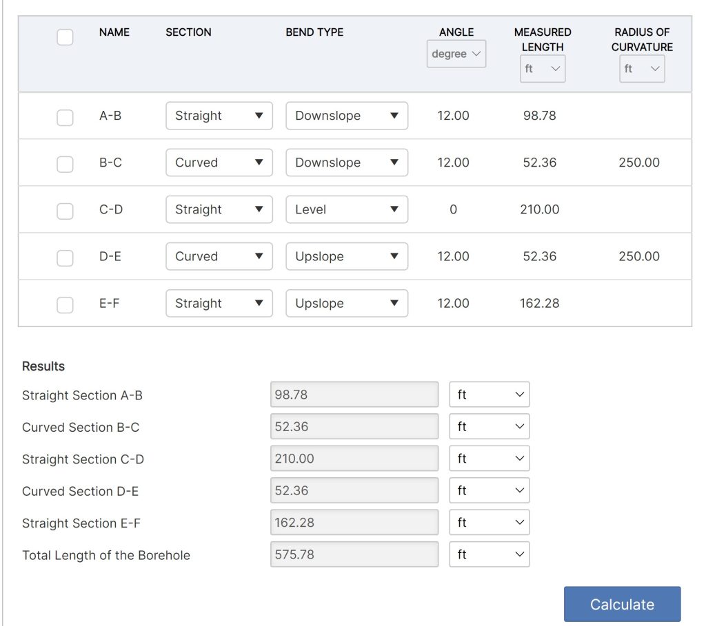
- Downslope: Straight Section A – B (Vertical)
- Pipe Entry Angle A – B [degree]
- Measured Length [ft]
- Downslope:
Curved Section B – C (Vertical)- Bend Angle B – C [degree]
- Radius of Curvature B – C [ft]
- Measured Length [ft]
- Straight Section C – D (Horizontal)
- Horizontal Angle[degree]
- Measured Length [ft]
- Upslope: Curved Section D – E (Vertical)
- Radius of Curvature D – E
- Measured Length [ft]
- Upslope: Straight Section E – F (Vertical)
- Pipe Exit Angle[degree]
- Measured Length [ft]
*The design changes based on borehole design (section configuration)
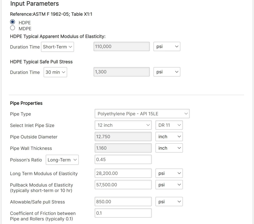
Pipe Properties:
- Pipe Type
- Select Inlet Pipe Size (in)
- Pipe Outside Diameter (in)
- Pipe Wall Thickness(in)
- Standard Dimension Ratio (DR)
- Long Term Modulus of Elasticity (psi)
- Poisson’s Ratio
- Long Term Modulus of Elasticity
- Pullback Modulus of Elasticity (typically short-term or 10 hr)
- Allowable Safe Pull Stress (psi)
- Coefficient of Friction between Pipe and Rollers (typically 0.1)
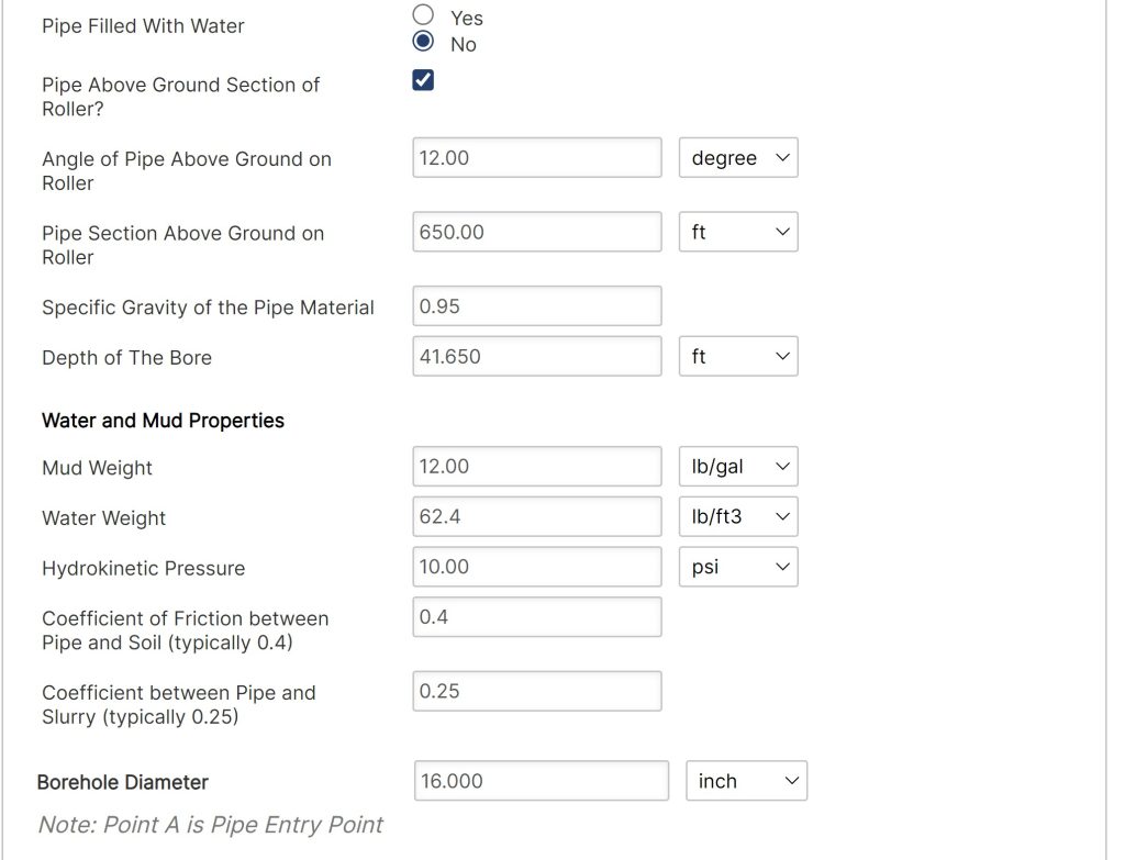
- Pipe Filled with Water (Y/N)
- Pipe Above Ground Section of Roller (Check Box)
- Angle of pipe Above Ground on Roller (°)
- Pipe Section Above Ground on Roller (ft.)
- Specific Gravity of Pipe Material
- Depth of The Bore
Water and Mud Properties:
- Mud Weight (lbs./gal)
- Water Weight(lbs./ft3)
- Hydrokinetic Pressure
- Coefficient of Friction between Pipe and Soil (typically 0.4)
- Coefficient between Pipe and Slurry (typically 0.25)
- Borehole Diameter
Borehole:
- Borehole Diameter (in)
Outputs/Reports
Results:
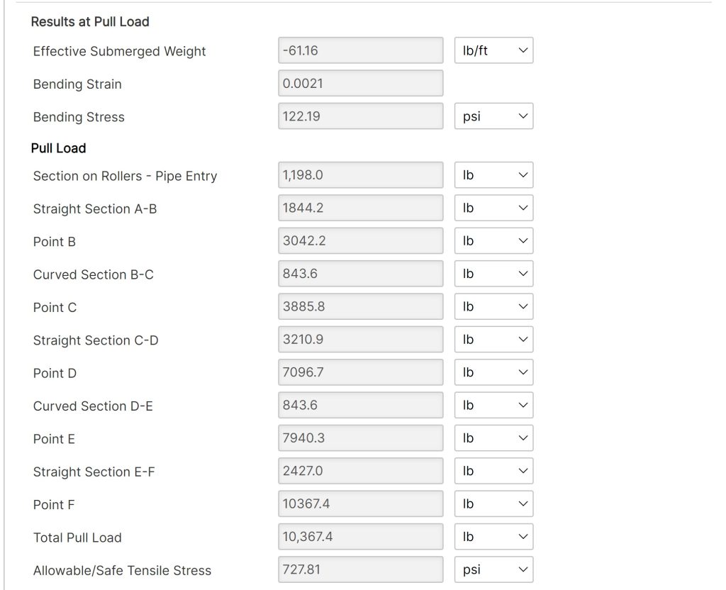
- Effective Submerged Weight
- Bending Strain
- Bending Stress
- Pull Load Section on Rollers – Pipe Entry
- Pull Load Straight Section A-B
- Pull Load at Point B
- Pull Load Curved Section B-C
- Pull Load at Point C
- Pull Load Straight Section C-D
- Pull Load at Point D
- Pull Load Curved Section D-E
- Pull Load at Point E
- Pull Load Straight Section E-F
- Pull Load at Point F
- Total Pull Load
- Allowable/Safe Tensile Stress
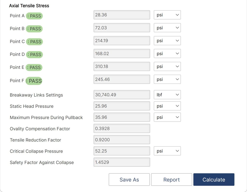
- Axial Tensile Stress at Point A: PASS
- Axial Tensile Stress at Point B: PASS
- Axial Tensile Stress at Point C: PASS
- Axial Tensile Stress at Point D: PASS
- Axial Tensile Stress at Point E: PASS
- Tensile Stress at Point F: PASS
- Breakaway Links Settings
- Static Head Pressure
- Maximum Pressure During Pullback
- Ovality Compensation Factor
- Tensile Reduction Factor
- Critical Collapse Pressure
- Safety Factor Against Collapse
References
- Willoughby, David (2005). Horizontal Directional Drilling, McGraw-Hill, New York, ISBN 0-87814-395-5. v.
- Willoughby, David, Training – Horizontal Directional Drilling, TTI, November 2016
- HDD Consortium. (2001). Horizontal directional drilling, good practices guidelines, HDD Consortium.
- Horizontal Directional Drilling Training Manual, Horizontal Drilling International, February 1999
- Skonberg, Eric R. II. Muindi, Tennyson M. (2014). Pipeline Design for Installation by Horizontal Directional Drilling, American Society of Civil Engineers. Horizontal Directional Drilling Design Guideline Task Committee.
- “Installation of Pipelines by Horizontal Directional Drilling”, PRCI Report PR-227-9424
- Nayyar, Mohinder L. (1992). Piping Handbook, 6th Edition, McGraw-Hill, New York, NY.
- AWWA (2006), PE Pipe Design and Installation, M55, American Water Works Association, Denver, CO
- ASTM (1962), PPI Handbook
AUGER BORING – Casing is jacked into the ground as a rotating auger works simultaneously to remove the excavated soil. It is commonly used in applications where settlement is a concern: under highways, railways and levies. Also known as a dry bore.
BENTONITE – A natural clay material used as a basic ingredient for drilling muds and lubricants to facilitate ease of installation.
BORE OR BOREHOLE – drilling term – The elongated cavity created by the drilling process. Often the borehole is not a void, but rather a hole filled with drilling mud and cuttings. Well casing is pulled or pushed into the borehole to complete a well.
CASING – drilling term – The non-perforated or non-slotted pipe that comprises the entry and exit sections of a horizontal well, as opposed to the well screen. Surface casing is a pipe that is set through loose surficial deposits to stabilize the bore, so the deeper sections can be drilled without difficulty from caving or collapse in the upper section of the borehole.
CROSSING – A pipeline installation designed to pass beneath a surface obstruction. Examples of crossings include roads, railway tracks, water bodies, pipeline corridors, and utilities.
DRILLING MUD – drilling material – aqueous slurry that is used during drilling to transport drill cuttings from the borehole, prevent borehole collapse and provide lubrication for the drill string. Most horizontal drilling uses drilling mud of some sort, although in some conditions it is possible or preferable to drill using air or water. Drilling mud made be made using the mineral bentonite, synthetic or natural polymers, or some combination of the two.
DRILL RIG – A trenchless machine that installs pipes and cables by drilling a pilot hole that can be enlarged (if necessary), and then pulling the product line.
ENTRY POINT – The starting location of the crossing where the drill enters the ground.
EXIT POINT – The end location of the crossing.
FORWARD REAMER – drilling tool – A type of reamer used to enlarge the diameter of the borehole in a blind or single-entry well.
HORIZONTAL DIRECTIONAL DRILLING (HDD) – A surface-based trenchless technology that involves a horizontal bore under the surface along a planned pathway. Once the HDD creates a bore of a suitable size – which may require one or multiple passes by the drilling apparatus – the conduit or pipe is pulled into the bore and connections are made to the appropriate utilities.
OPEN CUT – Underground construction method involving excavation from ground level to the level required for the installation, maintenance, or inspection of a pipe, conduit, or cable. Upon completion of the work, the trench is backfilled, and the surface restored. Backhoe excavation is an example of open-cut construction.
PILOT BORE – drilling term – The initial boring made in a horizontal well installation. The pilot bore is steered, using any of several technologies, from a designated entry point, along a predetermined bore path, to a designated endpoint, either at the ground surface or at depth. The pilot bore subsequently may be reamed to a larger diameter to accommodate the desired size well screen and casing.
PIPE PULLING – Method used to replace small diameter pipes by attaching new product pipe to the existing pipe, which is then pulled out of the ground.
POTHOLE – drilling term – a small hole excavated from the surface to a buried utility in order to provide positive verification of its location.
REAMER – drilling tool – a cutting tool used to enlarge the diameter of a borehole after the pilot bore has been drilled.
FAQ
-
HDD Power Tool?
Horizontal Directional Drilling or HDD, is a method of installing steel or polyethylene pipe, conduit, or cables in a designed bore path, by using a drilling rig, with a minimal footprint to the environment. HDD process represents a significant improvement over traditional open cut and disturbance methods for installing pipelines beneath obstructions, such as rivers or roads, which require specialized construction attention. To take full advantage of the benefits offered by horizontal directional drilling and produce designs which can be efficiently executed in the field, design engineers need a working knowledge of the process with the appropriate HDD software. Check Out
-
HDD – Version Capability Matrix
Calculations and functions involving the capabilities that HDD can provide. Check Out
-
HDDPT Process to Import KML/KMZ and Shape Files?
Here relies the step-by-step procedure of importing files and having them project accurate calculations to your reports. Check Out
-
How to Calculate a Compound Angle?
The HDD PowerTool program will calculate the compound data based on the horizontal and vertical data you enter.
For example: In the below screenshot, under curve, select the compound. You may then input 2 data elements for the horizontal and vertical part of the bend. The program will then calculate the compound. Check Out
-
Update on the Latest Technical Capabilities of the HDDPT?
Steel cased crossings have been used to avoid load considerations, unstable soil conditions, third party mechanical damage or when conditions dictated by regulatory or sound engineering practices. However, due to a variety of factors such design, installation, construction practices, materials, coatings, etc. have caused problems with protecting the carrier pipe within the casing. Check Out
-
Combined Stresses and Limitations for Both Liquid & Gas HDD?
HDD combined stresses can be analyzed by calculating the maximum shear stress on a small element in the pipeline. Maximum shear stress should be limited to 45% of the SMYS of the pipe (ASME/ANSI B31.4). This is in accordance to PRCI report PR-227-9424 from the findings and conclusions of those companies who performed and approved the research work, However, the question comes up from time to time that the B31.4 code can be converted to B31.8’s code application. Check Out
-
Hydraulic Fracture Analysis Geological Layers Data Input?
Some typical values of soil friction angle are given below for different USCS soil types at normally consolidated condition unless otherwise stated. These values should be used only as guideline for geotechnical problems; however, specific condition of each engineering problem often needs to be considered for an appropriate choice of geotechnical parameters. Check Out