
Introduction
The Pipeline Toolbox is home to many tools and calculators. The PLTB User’s Guide presents information, guidelines and procedures for use during design, construction, operations and integrity tasks for field or office applications.
In today’s competitive and changing environment, it is crucial that pipelines and associated facilities create and sustain value for their stakeholders. This value can only be achieved by incorporating dependability into the pipeline system, in whole or in part. Dependability characteristics address not just availability and reliability as the probability of successful performance, but also identify other potential risk exposures such as degradation and wear out that advocate the need for maintenance and logistic support to sustain “problem free” pipeline and facility operation. The following module contains a few calculations that can address some areas and tasks conducted on facilities to ensure greater levels of safety and operation.
Module/Application
- API 520 – Relief Valves Requiring No Capacity Certification
- API 520 – Relief Valves Requiring Capacity Certification
- Reinforcement of Welded Branch Connection
- Relief Valve: Reactive Force
References
- ASME – Boiler and Pressure Vessel Code, Section VIII
- API – RP 520 Part 2
- ASME B31.8 Gas Transmission and Distribution Piping Systems
- ASME B31.3, B31.4 and B31.8 – Full Encirclement Sleeves (See Appendices)
Appendix
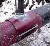
Even though Technical Toolboxes does not provide software for a full-encirclement reinforcing saddles, many operators use them to provide reinforcement for branch outlets in accordance with ASME B31.3, B31.4, B31.8 and other applicable design codes. Full-encirclement reinforcing saddles are designed to fully encircle the run pipe however; they are not designed to be pressure retaining devices. To avoid gas entrapment during welding and to prevent pressure containment, should a leak develop underneath the saddles; these saddles should be provided with a vent to allow escaping product.
A typical field applied Full Encirclement Reinforcement Weldment Saddle is shown below:

FAQ
-
Validation check: Reinforcement of Welded Branch Connection?
This table highlights the list of validation checks that are in effect in the PLTB Gas > Pipeline Facilities> Reinforcement of Welded Branch Connection – ASME B31.8 calculation. Check Out
-
Orifice Coefficient for Hot Tap Sizing?
When a compressible fluid, such as natural gas or air, is passed through an orifice, the rate of flow is determined by the area of the orifice opening; the absolute upstream pressure is 𝑃1; and the absolute downstream pressure is 𝑃2: unless the ratio 𝑃2/𝑃1. equals or is less than the critical ratio. When 𝑃2/𝑃1 equals or is less than the critical ratio downstream pressure no longer effects rate of flow through the orifice, and flow velocity at the vene contracta is equal to the speed of sound in that fluid under that set of condition. This is commonly referred to as critical or sonic flow. Orifice equations are therefore classified as “sonic” or “subsonic” equations. Check Out
-
How is Required Area calculated for Branched Weld Connection?
The calculation is using the following is the equation that we use for A3 – REQUIRED AREA
A3 = Ar – A1-A’2
where:
Ar = Reinforcement Required
A1= Reinforcement Provided
A’2 = Corrected Effective Area