
Introduction
Sizing of regulator is performed using the Universal Gas Equation:
Subsonic Flow Equation
Q = C_{g} P_1 \sqrt{\frac{520}{G_f T} \sin \left[ \left(\frac{3417}{C_1}\right) \sqrt{\frac{\Delta P}{P_1}} \right]}
Q = C_{g} P_1 \sqrt{\frac{520}{G_f T} \sin \left[ \left(\frac{3417}{C_1}\right) \sqrt{\frac{\Delta P}{P_1}} \right]}
Where:
𝑄 =Gas Flowrate (scf/h)
𝐺𝑓 = Gas Specific Gravity
𝑇 = Absolute Temperature (°R)
𝐶𝑔 = Gas Sizing Coefficient
𝐶𝑣 = Liquid Sizing Coefficient
𝐶1 = 𝐶𝑔/𝐶𝑣
𝑃1 = Gas Sizing Coefficient
Δ𝑃 = 𝑃1 − 𝑃2 − Differential Pressure Across Valve
𝑃2 = Outlet Pressure (psia)
Sonic Flow Equation is Reduced to:
Q=C_gP_1\sqrt{\frac{520}{G_fT}}
Q=C_gP_1\sqrt{\frac{520}{G_fT}}Case Guide
Part 1: Create Case
- Select the Regulator & Station Piping Sizing application from the Regulator & Meters Module
- To create a new case, click the “Add Case” button
- Enter Case Name, Location, Date and any necessary notes.
- Fill out all required Parameters.
- Make sure the values you are inputting are in the correct units.
- Click the CALCULATE button to overview results.
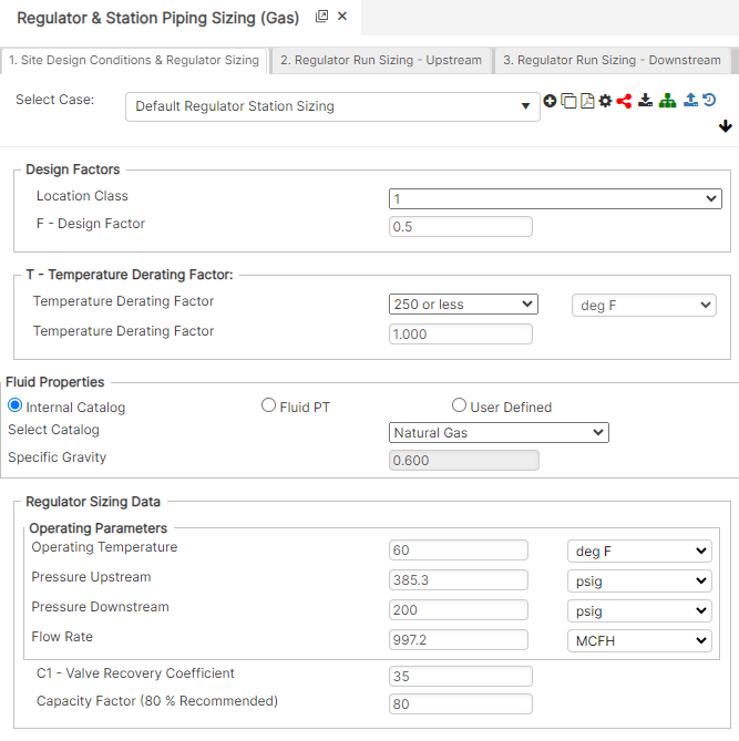
Input Parameters
- Class Location
- Temperature
- F – Design Factor
- T – Temperature Derating Factor
- Gas Specific Gravity
- Regulator Sizing Data
- P1 – Inlet Pressure
- P2 – Outlet Pressure
- Q – Flow Rate
- Gas Specific Gravity
- Flowing Gas Temperature
- C1 – Valve Recovery Coefficient
- Capacity Factor (80% Recommended)
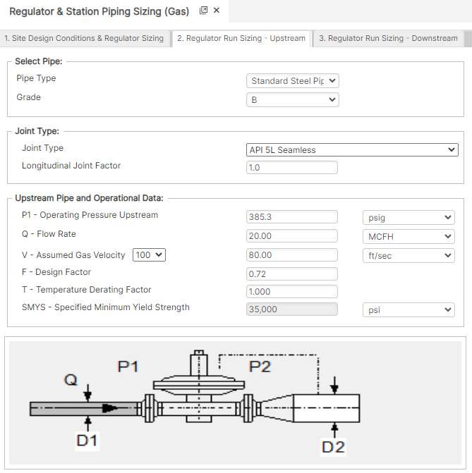
- Upstream Pipe and Operational Data
- P1 – Operating Pressure – Upstream
- Q – Flow Rate
- V – Assumed Gas Velocity
- F – Design Factor
- T – Temperature Derating Factor
- SMYS – Specified Minimum Yield Strength
- E – Longitudinal Joint Factor
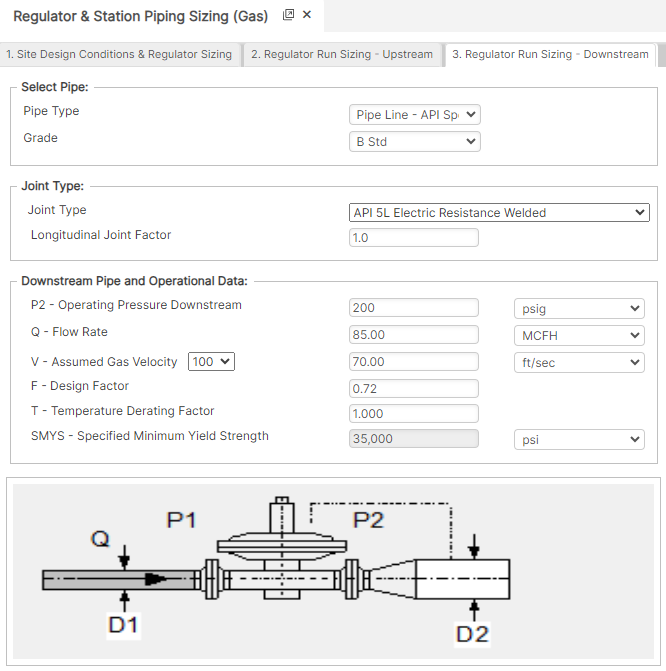
- Downstream Pipe Operational Data
- P2 – Operating Pressure – Downstream
- Q – Flow Rate
- V – Assumed Gas Velocity
- F – Design Factor
- T – Temperature Derating Factor
- SMYS – Specified Minimum Yield Strength
- E – Longitudinal Joint Factor
Part 2: Outputs/Reports
- If you need to modify an input parameter, click the CALCULATE button after the change.
- To SAVE, fill out all required case details then click the SAVE button.
- To rename an existing file, click the SAVE As button. Provide all case info then click SAVE.
- To generate a REPORT, click the REPORT button.
- The user may export the Case/Report by clicking the Export to Excel icon.
- To delete a case, click the DELETE icon near the top of the widget.
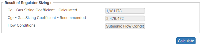
Results
- Regulator Sizing Results
- Cg – Gas Sizing Coefficient – Calculated
- Cgr – Gas Sizing Coefficient – Recommended
- Flow Conditions:
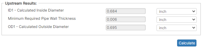
- Upstream Results
- ID1 – Calculated Inside Diameter (in)
- Minimum Required Pipe Wall Thickness (in)
- OD1 – Calculated Outside Diameter (in)
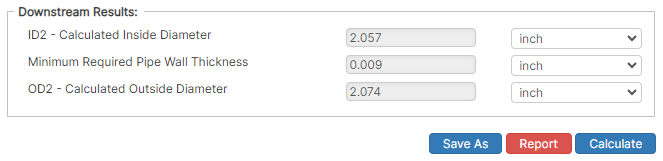
- Downstream Results
- ID1 – Calculated Inside Diameter (in)
- Minimum Required Pipe Wall Thickness (in)
- OD1 – Calculated Outside Diameter (in)
References
- AGA Report No. 3 – Orifice Metering of Natural Gas and other Related Hydrocarbon Fluid – Parts 1-4