
Introduction
This is a common type impressed current ground bed system used to catholically protect large segments of pipelines as well as pump or compressor station piping.
It requires many anodes to be effective in either multiple i.e. in line perpendicular as specific intervals to the pipeline system or distributed (random) as used in station piping.
R=\frac{0.0521\rho}{L}[ 2.3\log{\frac{8L}{d} } -1 + \frac{2L}{s}2.3 \log{0.655N}]
R=\frac{0.00521*\rho}{N*L}[ 2.3\log{\frac{8L}{d} } -1 + \frac{2L}{s}2.3 \log{0.655N}]Where:
𝑅 — Anode resistance to earth(Ohms)
𝐿 — Anode length(ft)
𝜌 — Actual soil resistivity(Ohm/cm)
𝑑 — Anode actual diameter(ft)
𝑁 — Number of anodes in parallel
𝑠 — Anode spacing(ft)

Case Guide
Part 1: Create Case
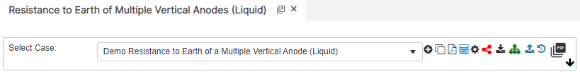
- Select the Resistance to Earth of Multiple Vertical Anode application from the Cathodic Protection Module
- To create a new case, click the “Add Case” button
- Enter Case Name, Location, Date and any necessary notes.
- Fill out all required parameters.
- Make sure the values you are inputting are in the correct units.
- Click the CALCULATE button to overview results.
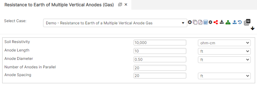
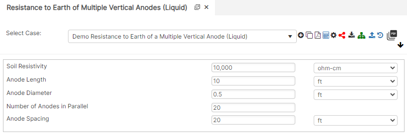
Input Parameters
- Soil Resistivity (ohm-cm)
- Anode Length (ft)
- Anode Diameter (ft)
- Number of Anodes in Parallel
- Anode Spacing (ft)
Part 2: Outputs/Reports
- If you need to modify an input parameter, click the CALCULATE button after the change.
- To SAVE, fill out all required case details then click the SAVE button.
- To rename an existing file, click the SAVE As button. Provide all case info then click SAVE.
- To generate a REPORT, click the REPORT button.
- The user may export the Case/Report by clicking the Export to Excel icon.
- To delete a case, click the DELETE icon near the top of the widget.
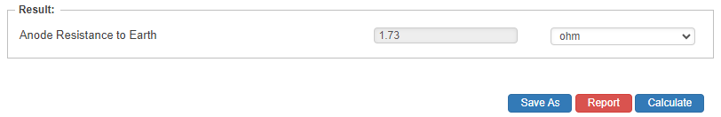
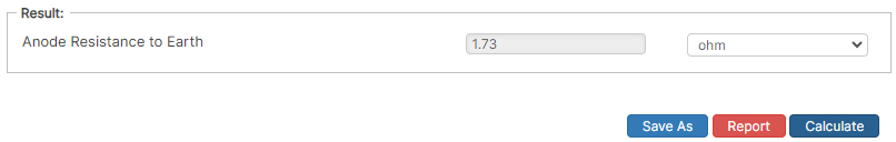
Results
- Anode Resistance to Earth (ohm)
References
- NACE Standard Practices 0169 – Latest Edition “Control of Corrosion on Underground or Submerged Metallic Piping Systems”
- Uhlig’s Corrosion Handbook (2nd Edition) Edited by: Revie, R. Winston © 2000 John Wiley & Sons
- ISO 15589-2 Petroleum and Natural gas Industries Cathodic Protection Pipeline Transportation Systems
- Pipeline Corrosion and Cathodic Protection, Third Edition, Gulf Publishing Company
FAQ
-
ASME B31G Original/Modified and RSTRENG?
ASME B31.G Original and Modified (0.85) are Level 1 assessment along with most other metal loss calculations that are limited to pits and short lengths of pitting clusters. RSTRENG is a Level 2 metal loss calculation; however, it is not limited just to pits, but most lengths of pitting i.e., 2500 mm (100 inches) using interaction rules that is not uncommon on some pipelines. Check Out
-
Preventative and Corrective Measures to Control Corrosion Pitting?
A corrosion rate needed to set the re-inspection interval, reassess the performance metrics and their current applicability, plus to ensure the assumptions made are correct. At each direct examination where corrosion pitting is found, the operator should measure and record each pitting cluster. Check Out
-
Estimating Internal Corrosion Rates?
Internal corrosion is most likely to occur where water first accumulates. Predicting these locations of water accumulation serve as a method for prioritizing local examinations. Predicting where water first accumulates requires knowledge about the multiphase flow behavior in the pipe requiring certain data. Check Out
-
Estimating External Corrosion Rates?
All corrosion defects found during each direct examination should be measured, documented, and remediated as needed. At each excavation, the pipeline operator should measure and record generic environmental characteristics (such as soil resistivity, hydrology, drainage etc.). Check Out