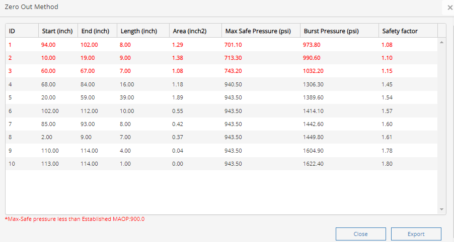
The zero-out method (ZOM) data is available to be viewed in a separate screen which is also available for export to an excel spreadsheet to be compared with data post-execution of the zero-out method.
See top menu Zero Out Method Table as shown below. These results are from the calculations using RSTRENG.

It should be noted that this pipeline example is a 0.72 design with a safety factor of 1.39. This table can assist the pipeline operator in the determination of making the appropriate repairs with composite/steel sleeves to bring the pipeline to a safe operating pressure. Most operators use the combination of safety factors and max safe operating pressure to make critical engineering assessments (ECAs).
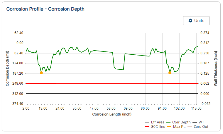
Effective Areas Graphed
Zero Out effective area on the graph using the profile bar is displayed in the image below.

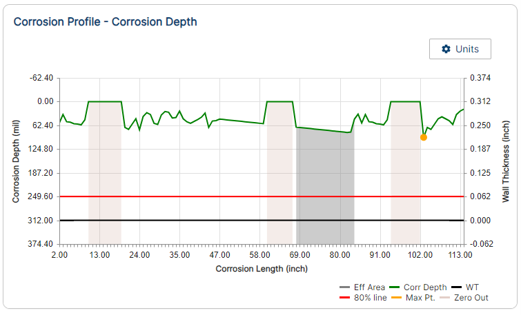
The image below represents an RSTRENG© plot when the above case is re-calculated until all areas are to be repaired.

Results of Zero Out Method Table with repairs made shown below:

It should be noted that the user has the option to keep running the Zero Out Method PRCI RSTRENG 2.7 Intro_6.png(Single Method) until the desired Safety Factor and Max Safe Pressure meets their criteria for safety. For example, there could be safety concerns such as a geotechnical issue or a dwelling that is too close.
Additional Resources
Technical Toolboxes offers training webinars on these upgrades as well as RSTRENG© on-site training with certification. RSTRENG© training courses are also offered with defect analysis understanding from one half-day, one day, and one 1/2 days depending on your needs. Review our website under the Training section to sign up for these courses.
For support and other software questions, please check out the Support Tab on the Technical Toolboxes Website or our Support Desk Portal.
References
- PRCI – A Modified Criterion for Evaluating the Remaining Strength of Corroded Pipe
- PRCI – Database of Corroded Pipe Tests
- PRCI – Continued Validation of RSTRENG
- For additional information please see reports that are furnished by Pipeline Research Council International, Inc. (PRCI) using the following link. https://www.prci.org/Research/Corrosion/CORRProjects/EC-6-1/4153/15495.aspx
- NACE Standard RPO102 (latest revision), “In-Line Inspection of Pipelines” Houston, TX
- NACE Standard RP0313 (latest revision), “Guided Wave Applications for Pipelines”, Houston, TX
- NACE Standard RP0502 (latest revision), “Pipeline External Corrosion Direct Assessment Methodology”, Houston, TX
- ASME B31.8 (latest revision), Gas Transmission and Distribution Piping, New York, New York
- ASME B31.8S (latest revision), Gas Transmission and Distribution Piping, New York, New York
- ASME B31.G (latest revision), ASME B31G – Manual for Determining the Remaining Strength of Corroded Pipelines (RSTRENG), New York, New York
Appendices
- Remaining Strength of Corroded Pipe (RSTRENG) Assessment Procedure, Joe Pikas
- Preventative Measures to Control Corrosion Pitting, Joe Pikas
FAQ
-
RSRTENG Tips
Technical Toolboxes receives many RSTRENG questions throughout the year; however, most of them are not related to operating the software. These questions are related to procedures, definitions, and field repairs.
When metal loss features in pipelines are detected by in-line inspection (ILI), a decision to replace, repair, and assess remaining features. This decision is based on the prediction of the failure pressure of the corroded pipeline and must adhere to the US Code of Federal Regulations (CFR) Title 49, Parts 192 and 195, that stipulates that ASME B31G or RSTRENG be used to assess the remaining strength of corroded pipelines. Check Out
-
RSTRENG (Effective Area) Calculations
What Actions must be Taken to Address Integrity Issues?
According to DOT 192.933 a calculation of the remaining strength of the pipe shows a predicted failure pressure less than or equal to 1.1 times the maximum allowable operating pressure at the location of the anomaly. Suitable remaining strength calculation methods include, ASME/ANSI B31G; RSTRENG; or an alternative equivalent method of remaining strength calculation. Check Out
-
Preventative and Corrective Measures to Control Corrosion Pitting
A corrosion rate needed to set the re-inspection interval, reassess the performance metrics and their current applicability, plus to ensure the assumptions made are correct. At each direct examination where corrosion pitting is found, the operator should measure and record each pitting cluster. The aforementioned data are then used to estimate corrosion rates. Average corrosion rates are related to the environment, depth of pitting and years of in-service. Check Out
-
Estimating Internal Corrosion Rates?
Internal corrosion is most likely to occur where water first accumulates. Predicting these locations of water accumulation serve as a method for prioritizing local examinations. Predicting where water first accumulates requires knowledge about the multiphase flow behavior in the pipe requiring certain data. The following are some general calculations based on flow conditions. Keep in mind that these are strictly estimates and do not consider the effects of temperature, wettability, MIC, pressure, hydrocarbon characterization, gas composition, etc. Check Out
-
Estimating External Corrosion Rates?
All corrosion defects found during each direct examination should be measured, documented, and remediated as needed. At each excavation, the pipeline operator should measure and record generic environmental characteristics (such as soil resistivity, hydrology, drainage etc.). These data have been used to estimate corrosion rates. Average corrosion rates related to soil resistivity are below in the following table with no CP. Check Out
-
ASME B31G Original/Modified and RSTRENG Overview
ASME B31.G Original and Modified (0.85) are Level 1 assessment along with most other metal loss calculations that are limited to pits and short lengths of pitting clusters. Check Out
-
RSTRENG update for 49 CFR § 192.714 and § 192.9.33
Based on U.S. federal regulations and industry guidance, a RSTRENG assessment for corrosion defects on onshore gas transmission pipelines under 49 CFR § 192.714 and § 192.9.33 must follow a series of steps to determine the pipe’s remaining strength and required repair action. RSTRENG is a Level 2 assessment method that uses the “effective area” approach to evaluate complex corrosion profiles. ASME B31.G Original and ASME B31.G Modified are a Level 1 assessment and use maximum depth and length to evaluate a single pitting area. Learn more
