The stress intensity factors associated with the three crack locations (weld toe, weld root and sleeve end) are a function of a number of parameters, including:
- Pipe geometry (OD/t)
- Sleeve geometry (thickness and length)
- Crack geometry (crack depth and length)
- Loading conditions
In order to understand the effect each of these parameters has on the stress intensity factors, a sensitivity study has been carried out. The following section presents a summary of the sensitivity study including highlighting the general trends regarding which factors are the largest contributors to the behavior of cracks in sleeve end fillets welds.
Summary of Sensitivity Study Matrix
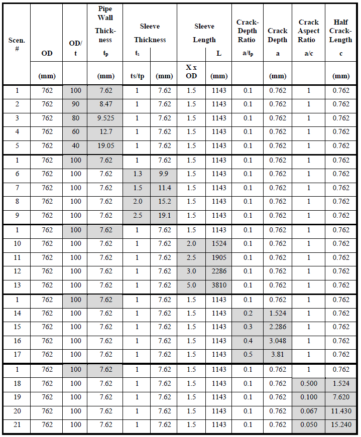
The sensitivity study has been carried out based on the matrix of scenarios presented in Table 6.1. The matrix includes 21 scenarios, covering the range of geometries for which the SIF equations were developed. Scenario 1 represents the baseline scenario, defined as:
- Pipe geometry: OD = 762 mm, tp = 7.62 mm (OD / tp = 100)
- Sleeve geometry: L = 1,143 mm (Ls / OD = 1.5), ts = 7.62 mm (ts / tp = 1.0)
- Crack Size: a = 0.762 (a / tp = 0.1), 2c = 1.524 (a / c = 1.0)
Each of the other 20 scenarios represents a variation on one of the governing geometry ratios, as summarized below:
- Scenarios 2 to 5 – varies OD / tp, from 90 to 40.
- Scenarios 6 to 9 – varies ts / tp, from 1.3 to 2.5.
- Scenarios 10 to 13 – varies Ls / OD, from 2.0 to 5.0.
- Scenarios 14 to 17 – varies a / tp, from 0.2 to 0.5.
- Scenarios 18 to 21 – varies a /c, from 0.5 to 0.05.
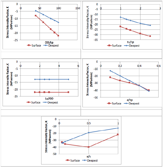
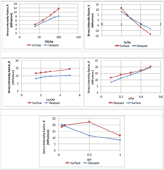
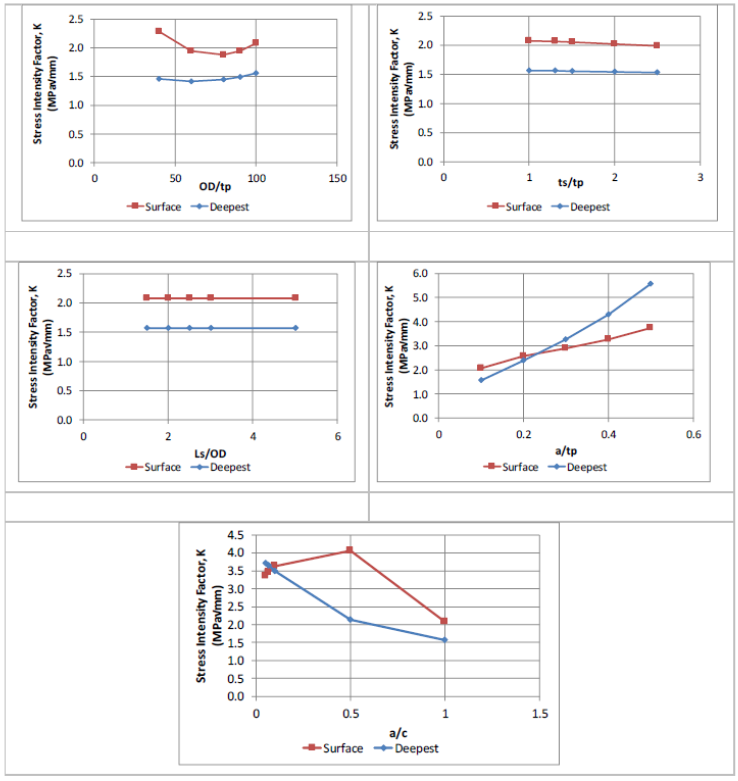
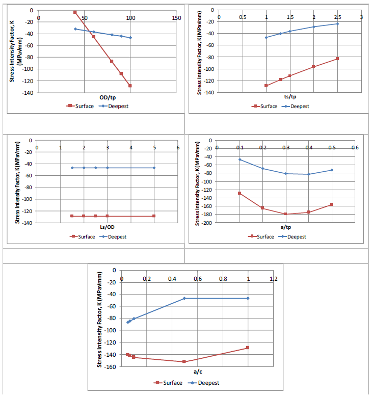
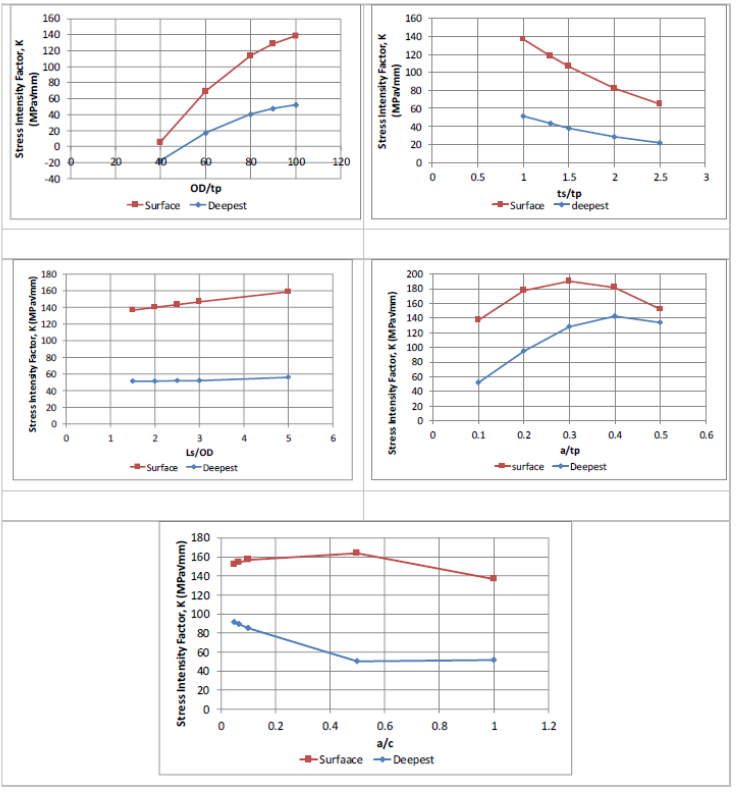
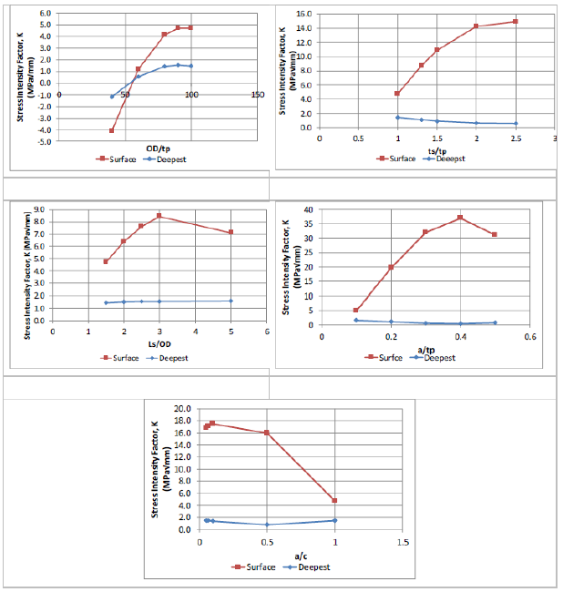
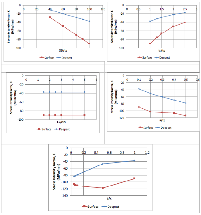
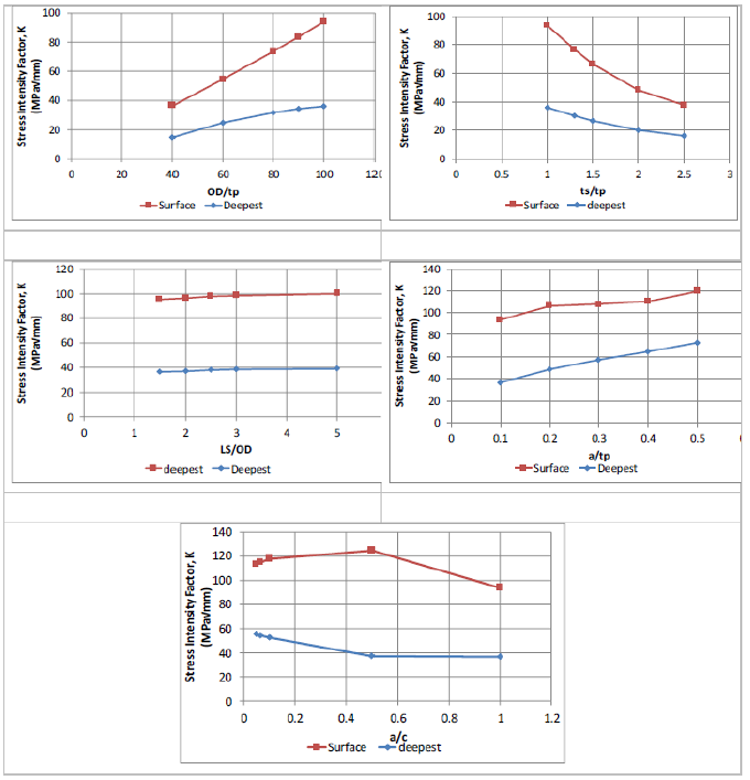
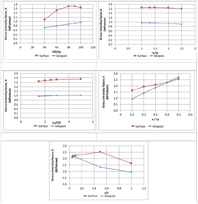
The stress intensity factors for unit applied stresses (for both the deepest point and the surface breaking point) were calculated for all 21 scenarios, at each of the three cracking locations, under all three loading conditions (pressure in pipe only, pressure in pipe and annulus and axial stress on carrier pipe). Plots of the calculated stress intensity factors for all the scenarios, as a function of the various geometry ratios, are presented in Figure 6.1 through Figure 6.9.
Sensitivity Study – Trends
Weld Toe cracking
There are several important trends identified for cracking at the weld toe of a sleeve end fillet weld.
For Pressure in Carrier Pipe Only
- For internal pressure in the carrier pipe only, all the stress intensity factors are negative, indicating the crack faces are closed. For such scenarios, failure of the crack through either fracture or plastic collapse is not a concern.
- The length of the sleeve plays an insignificant role in the stress intensity factor for pressure in the carrier pipe only.
For Pressure in the Carrier Pipe and Annulus
- In general, for pressure in the carrier pipe and annulus, the stress intensity factors are positive, indicating a crack at the weld toe is opening.
- For sleeve thicknesses (ts) more than 1.5x the pipe wall thickness (tp), the stress intensity factor may become negative, indicating crack face closure.
- The stress intensity factor at the deepest point tends to be higher than the stress intensity factor at the surface breaking point.
For Axial Tensile Stress on Carrier Pipe
- For axial stress applied to the carrier pipe the stress intensity factors are positive, indicating crack opening.
- The sleeve length has a negligible effect on the stress intensity factor for cracks in the weld toe. The stress intensity at the surface breaking point tends to be higher than at the deepest point for crack depths less than 30% of the pipe wall thickness (a/tp).
- This is due primarily to the presence of the fillet weld and the associated stress intensity magnification factor, which increases the stress intensity at the surface.
Combined Loading Scenarios
- For combined loading scenarios (i.e. pressure in pipe plus axial stress on the carrier pipe), the combined stress intensity factor may be positive and therefore such loading scenarios should be considered in the assessment (i.e. global bending loads applied to the carrier pipe that may cause local axial stress on the section of carrier pipe where a flaw may be located).
Weld Root Cracking
For Pressure in Carrier Pipe Only
- For internal pressure in the carrier pipe only, all the stress intensity factors are negative, indicating the crack faces are closed. For such scenarios, failure of the crack through either fracture or plastic collapse is not a concern.
- The length of the sleeve plays an insignificant role in the stress intensity factor for pressure in the carrier pipe only.
For Pressure in the Carrier Pipe and Annulus
- For pressure in the carrier pipe and annulus, the stress intensity factors are positive, indicating a crack at the weld root is opening.
- The stress intensity factor at the surface breaking point is higher than the stress intensity factor at the deepest point in the crack
For Axial Tensile Stress on Carrier Pipe
- For axial stress applied to the carrier pipe the stress intensity factors are positive, indicating crack opening.
- The stress intensity at the surface breaking point tends to be higher than at the deepest point.
Combined Loading Scenarios
- For combined loading scenarios (i.e. pressure in pipe plus axial stress on the carrier pipe), the combined stress intensity factor may be positive and therefore such loading scenarios should be considered in the assessment (i.e. global bending loads applied to the carrier pipe that may cause local axial stress on the section of carrier pipe where a flaw may be located.
Sleeve End Cracking
For Pressure in Carrier Pipe Only
- For internal pressure in the carrier pipe only, all the stress intensity factors are negative, indicating the crack faces are closed. For such scenarios, failure of the crack through either fracture or plastic collapse is not a concern.
- The length of the sleeve plays an insignificant role in the stress intensity factor for pressure in the carrier pipe only.
For Pressure in the Carrier Pipe and Annulus
- For pressure in the carrier pipe and annulus, the stress intensity factors are positive, indicating a crack at the weld root is opening.
- The stress intensity factor at the surface breaking point is higher than the stress intensity factor at the deepest point in the crack
For Axial Tensile Stress on Carrier Pipe
- For axial stress applied to the carrier pipe the stress intensity factors are positive, indicating crack opening.
- The stress intensity at the surface breaking point tends to be higher than at the deepest point.
Combined Loading Scenarios
- For combined loading scenarios (i.e. pressure in pipe plus axial stress on the carrier pipe), the combined stress intensity factor may be positive and therefore such loading scenarios should be considered in the assessment (i.e. global bending loads applied to the carrier pipe that may cause local axial stress on the section of carrier pipe where a flaw may be located.
Summary of Major SIF Trends
As summarized in the previous sections, many of the observable trends are similar for all three cracking locations and all three loading conditions considered. These include:
- The sleeve length generally plays a limited role in the calculated stress intensity factor.
- For internal pressure in the carrier pipe only, the calculated stress intensity factors tend to be negative, indicating crack face closure.
- For internal pressure in the carrier pipe and annulus, the calculated stress intensity factors tend to be positive.
- For axial stresses on the carrier pipe, the calculated stress intensity factors are positive.
- The stress intensity factors at the surface breaking point tend to be higher than those at the deepest point.
Appendices of Tables
References
- In the Matter of an Accident on 19 February 1985 near Camrose, Alberta on the Pipeline System of Interprovincial Pipe Line ”, National Energy Board, Canada, 1986.
- F. Cross and C.A. Robertson, “Northeast U.S. products line upgraded after major line break”, Oil and Gas Journal, February 15 1988, Vol. 86, No. 7, pp 35 40.
- “Development of Sleeve End Fillet Weld Fitness for Service Assessment Tools”, PRCI Contract Num- ber PR-214-114504, April 22, 2016.
- API 579-2/ASME FFS-1 “Fitness-for-Service, American Petroleum Institute and the American Soci- ety of Mechanical Engineers, June 2007.
FAQ
-
PRCI Hot Tap results not showing on reports
This can be attributed to one of the following reasons: Check Out
- Calculation not executed
- Engine Crash
- Update made to input data
-
PRCI Hot Tap Hardness value for Multipass Welds
For multiple pass welds the original hardness gets tempered so the hardness is reduced. The current model predicts a single pass weld so it is a worse case scenario since no tempering has occurred. Check Out
-
PRCI Hot Tap Hardness Model
The PRCI hardness model is the predicted Vickers hardness of the weld HAZ using a 10-kg load. The hardness curve is based on the Yurioka equations which are based on Vickers hardness with a 10-kg load. Check Out
-
How can we account for Sleeve/Fitting material?
The current model (V 4.2.2) doesnt allow predicting hardness of two different materials. The inability to predict hardness of two different materials is an issue with the current model. Check Out
-
Does the model consider the composition entered in the “Max Hardness” area for both the pipe and the sleeve?
The model does not currently allow for modeling two materials however a current project looking to update the model will allow this option (Hot Tap V5 will have this feature). Check Out
-
Validation checks enforce in PRCI Hot Tap Model
Below is a list of all input data entry validation checks that are integrated in the PRCI Hot Tap model. The model runs all the below input data range checks as part of the input data validation loop before the case model is executed. Check Out
-
Clarification on Heat input and Arc energy in Hot Tap Model
The reported value used for “Enter Heat Input” entry is the arc energy even though it is referred to as heat input. This has always been an issue since all the historical work on in-service welding always referred to arc energy as heat input and that has continued with this model. How the model addresses different welding process is by the arc efficiency option selection. Check Out
