The validation of the software calculations was carried out by comparing the SIFs calculated by the software with those calculated using detailed 3D linear elastic finite element models of each of the nine scenarios, where crack tip elements were used to calculate the SIFs all along the crack front. The FE analysis was carried out using the ANSYS 17.0 software package. approach.
Finite Element Model
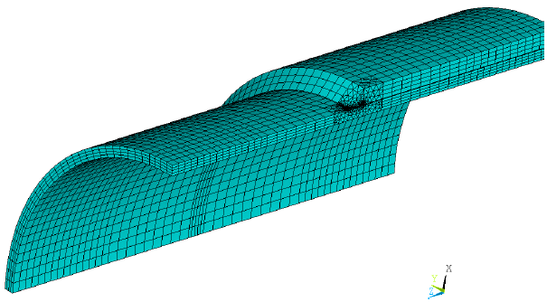
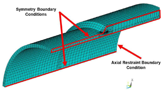
A sample 3D finite element model for the sleeve end flaw location is shown in Figure 5.1. As shown, in order to optimize computer analysis times, the models utilized a quarter symmetry representation of the pipe and sleeve assembly, with the crack located at one of the planes of symmetry.
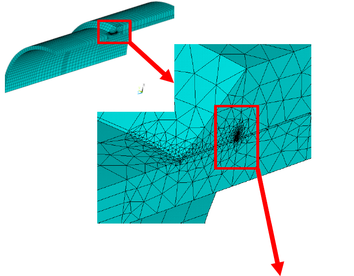
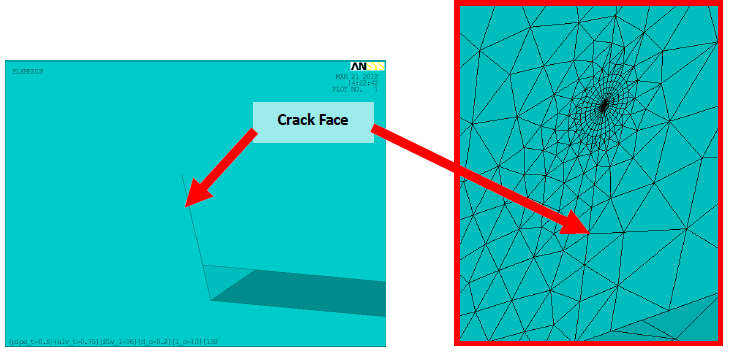
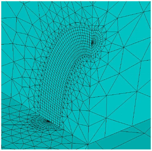
As shown in Figure 5.1, the models utilize a combination of 20 noded brick and 10 noded wedge elements to represent the pipe wall, the sleeve and the fillet weld. In the vicinity of the simulated crack front, the model utilizes a refined mesh, as shown in Figure 5.2 in order to capture the large stress gradients associated with the crack tip singularity. Figure 5.3 shows the meshing along the crack front (with one half of the elements removed for clarity).
The finite element models utilized linear elastic material properties to represent the material response, with a Young’s Modulus of 207 GPa and a Poisson’s ratio 0.3.
The boundary conditions applied in each model, shown in 5.4, are summarized below:
- Symmetry boundary conditions were applied to both planes of symmetry (i.e., on the surfaces located at 12 and 9 o’clock), where the symmetry boundary conditions prevent translation out of the plane of symmetry and rotations about the other two axes.
- Rigid axial constraints (i.e., UZ, along the axis of the pipe) were applied to both the pipe and sleeve cross section surfaces at one end of the model.
The finite element models assume the sleeve is installed with the pipe at zero internal pressure.
For the pressurized pipe loading scenarios, internal pressures were applied as uniform pressures to all of the areas on the inner surface of the pipe. For those scenarios where the annulus was assumed to be pressurized also, uniform pressures were also applied to the outer surfaces of the pipe that are inside the extent of the sleeve and all of the areas on the inner surface of the sleeve itself.
The tensile axial loads were applied as a unit pressure on the entire free face of the pipe cross-section (i.e., the face opposite the axial restraint).
Comparison of Results
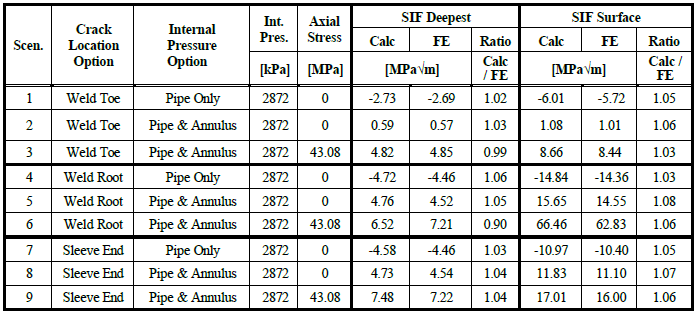
A summary of the SIFs calculated by the software and by the FEA is presented in 5.1. As shown, there is good agreement between the SIFs with the software calculated SIFs being within the error margins associated with the SIF equations developed in the original project.
References
- In the Matter of an Accident on 19 February 1985 near Camrose, Alberta on the Pipeline System of Interprovincial Pipe Line ”, National Energy Board, Canada, 1986.
- F. Cross and C.A. Robertson, “Northeast U.S. products line upgraded after major line break”, Oil and Gas Journal, February 15 1988, Vol. 86, No. 7, pp 35 40.
- “Development of Sleeve End Fillet Weld Fitness for Service Assessment Tools”, PRCI Contract Num- ber PR-214-114504, April 22, 2016.
- API 579-2/ASME FFS-1 “Fitness-for-Service, American Petroleum Institute and the American Soci- ety of Mechanical Engineers, June 2007.
FAQ
-
PRCI Hot Tap results not showing on reports
This can be attributed to one of the following reasons: Check Out
- Calculation not executed
- Engine Crash
- Update made to input data
-
PRCI Hot Tap Hardness value for Multipass Welds
For multiple pass welds the original hardness gets tempered so the hardness is reduced. The current model predicts a single pass weld so it is a worse case scenario since no tempering has occurred. Check Out
-
PRCI Hot Tap Hardness Model
The PRCI hardness model is the predicted Vickers hardness of the weld HAZ using a 10-kg load. The hardness curve is based on the Yurioka equations which are based on Vickers hardness with a 10-kg load. Check Out
-
How can we account for Sleeve/Fitting material?
The current model (V 4.2.2) doesnt allow predicting hardness of two different materials. The inability to predict hardness of two different materials is an issue with the current model. Check Out
-
Does the model consider the composition entered in the “Max Hardness” area for both the pipe and the sleeve?
The model does not currently allow for modeling two materials however a current project looking to update the model will allow this option (Hot Tap V5 will have this feature). Check Out
-
Validation checks enforce in PRCI Hot Tap Model
Below is a list of all input data entry validation checks that are integrated in the PRCI Hot Tap model. The model runs all the below input data range checks as part of the input data validation loop before the case model is executed. Check Out
-
Clarification on Heat input and Arc energy in Hot Tap Model
The reported value used for “Enter Heat Input” entry is the arc energy even though it is referred to as heat input. This has always been an issue since all the historical work on in-service welding always referred to arc energy as heat input and that has continued with this model. How the model addresses different welding process is by the arc efficiency option selection. Check Out
