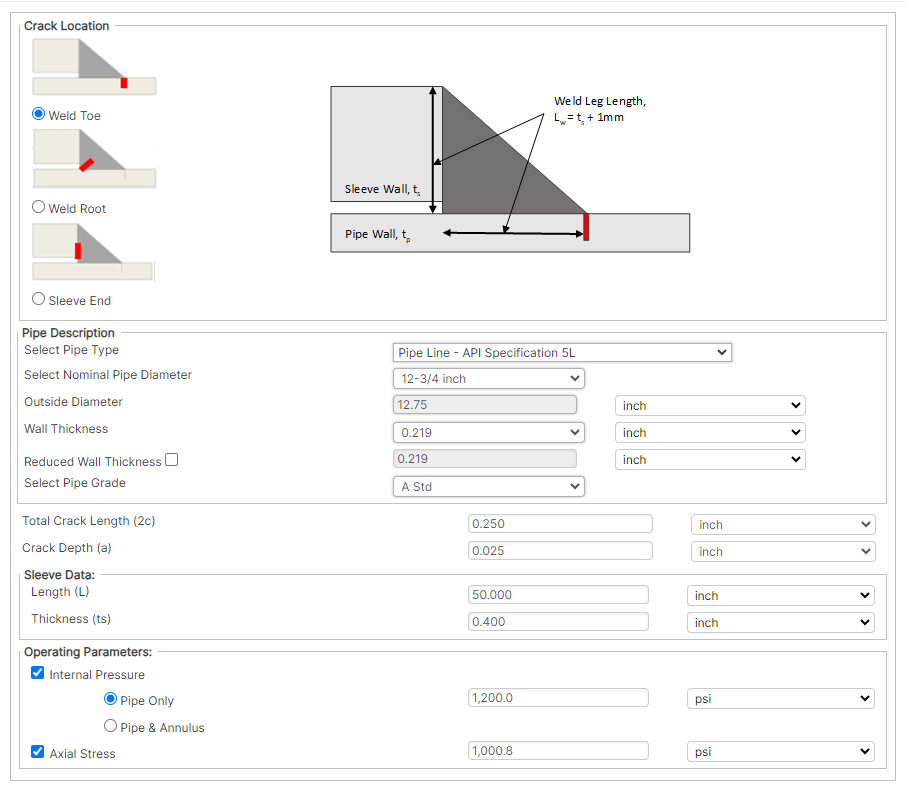
The initial steps to using the Sleeve End Fillet Weld (SEFW) consist of creating a New Case and selecting the appropriate Crack Location. The user should also select the appropriate Unit type (US or Metric) by clicking the button outlined in red in the image below.

Single Scenario

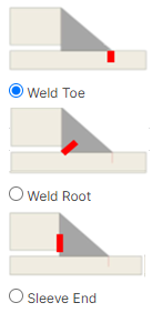
Crack Location

- Weld Toe – At the toe of the fillet weld between the sleeve and the carrier pipe
- Weld Root – At the root of the fillet weld, growing up through the throat of the weld
- Sleeve End – Between the end face of the sleeve and the vertical leg of the fillet weld (e.g. lack of fusion)
Pipe Description

- Outer Diameter (OD) – Outer diameter of the carrier pipe
- Wall Thickness (tp) – Wall thickness of the carrier pipe
- Reduced Wall Thickness – Wall thickness of the carrier pipe from the survey data (if available)
- Total Crack Length (2c) – Total surface length of the crack to be assessed
- Crack Depth (a) – Depth of the deepest point of the crack to be assessed
- Total Crack Length – The measurement of crack length on the carrier pipe
- Crack Depth – The measurement of the crack by its depth on the carrier pipe
Operational Parameters

- Internal Pressure – One of the following three selections
- None (axial stress only)
- In carrier pipe only
- In carrier pipe and pipe/sleeve annulus
(Difference between internal pressure at the time of sleeve installation and internal pressure being evaluated)
- Axial Stress – Axial stress on the carrier pipe. Could be due to axial thermal stresses or global pipe bending.
- Can be combined with the internal pressure loading options
References
- In the Matter of an Accident on 19 February 1985 near Camrose, Alberta on the Pipeline System of Interprovincial Pipe Line ”, National Energy Board, Canada, 1986.
- F. Cross and C.A. Robertson, “Northeast U.S. products line upgraded after major line break”, Oil and Gas Journal, February 15 1988, Vol. 86, No. 7, pp 35 40.
- “Development of Sleeve End Fillet Weld Fitness for Service Assessment Tools”, PRCI Contract Num- ber PR-214-114504, April 22, 2016.
- API 579-2/ASME FFS-1 “Fitness-for-Service, American Petroleum Institute and the American Soci- ety of Mechanical Engineers, June 2007.
FAQ
-
PRCI Hot Tap results not showing on reports
This can be attributed to one of the following reasons: Check Out
- Calculation not executed
- Engine Crash
- Update made to input data
-
PRCI Hot Tap Hardness value for Multipass Welds
For multiple pass welds the original hardness gets tempered so the hardness is reduced. The current model predicts a single pass weld so it is a worse case scenario since no tempering has occurred. Check Out
-
PRCI Hot Tap Hardness Model
The PRCI hardness model is the predicted Vickers hardness of the weld HAZ using a 10-kg load. The hardness curve is based on the Yurioka equations which are based on Vickers hardness with a 10-kg load. Check Out
-
How can we account for Sleeve/Fitting material?
The current model (V 4.2.2) doesnt allow predicting hardness of two different materials. The inability to predict hardness of two different materials is an issue with the current model. Check Out
-
Does the model consider the composition entered in the “Max Hardness” area for both the pipe and the sleeve?
The model does not currently allow for modeling two materials however a current project looking to update the model will allow this option (Hot Tap V5 will have this feature). Check Out
-
Validation checks enforce in PRCI Hot Tap Model
Below is a list of all input data entry validation checks that are integrated in the PRCI Hot Tap model. The model runs all the below input data range checks as part of the input data validation loop before the case model is executed. Check Out
-
Clarification on Heat input and Arc energy in Hot Tap Model
The reported value used for “Enter Heat Input” entry is the arc energy even though it is referred to as heat input. This has always been an issue since all the historical work on in-service welding always referred to arc energy as heat input and that has continued with this model. How the model addresses different welding process is by the arc efficiency option selection. Check Out
