
Introduction
This application calculates the stress induced on a pipeline from vibrational construction equipment, such as impact pile drivers, hydraulic breakers, or jackhammers. The vibrations caused by operating this equipment stresses the pipeline, potentially causing integrity issues. This calculator allows you the user to make accurate estimates for the vibrational stress added to the pipeline.
Notably, the calculator does not calculate ANY of the loading stresses (both from the soil, and from the equipment itself). Further analysis using one of our crossing calculators, such as CEPA Grid Load, may be necessary.
Peak Particle Velocity
The peak particle velocity (PPV) caused by the vibrational equipment can induce stress on the pipe. The method to calculate PPV differs depending on the equipment used.
Impact Pile Driver
For an impact pile driver:
\text{PPV}_{\text{Impact Pile Driver}} = \text{PPV}_\text{ref} \left(\frac{25}{D}\right)^n \times \sqrt{\frac{E_\text{equip}} {E_\text{Ref}} }text{PPV}{text{Impact Pile Driver}} = text{PPV}text{ref} left(frac{25}{D}right)^n times sqrt{frac{E_text{equip}} {E_text{Ref}} }
Where:
PPVimpact pile driver − Peak particle velocity at the pipe cause by the pile driver (in/sec)
PPVref = 0.65 in/sec for a reference pile driver at 25 feet.
n – Soil attenuation coefficient
Hydraulic Breaker
For a hydraulic breaker:
\text{PPV}_{\text{Hydraulic Breaker}} = \text{PPV}_\text{ref} \left(\frac{25}{D}\right)^n \times \sqrt{\frac{E_\text{equip}} {E_\text{Ref}} }text{PPV}{text{Impact Pile Driver}} = text{PPV}text{ref} left(frac{25}{D}right)^n times sqrt{frac{E_text{equip}} {E_text{Ref}} }
Where:
PPVhydraulic breaker − Peak particle velocity at the pipe cause by the pile driver (in/sec)
PPVref = 0.24 in/sec for the reference hydraulic breaker at 25 feet.
n – Soil attenuation coefficient
General Equipment
For vibratory rollers, large bulldozers, caisson drilling, jackhammers, and crack-and-seat Operations:
\text{PPV}_{\text{Equipment}} = \text{PPV}_\text{ref} \left(\frac{25}{D}\right)^ntext{PPV}{text{Equipment}} = text{PPV}text{ref} left(frac{25}{D}right)^n
Where:
PPVEquipment − Peak particle velocity at the pipe cause by the pile driver (in/sec)
n – Soil attenuation coefficient
PPVref = Reference PPV at 25 feet for the given equipment, specified in the table below.
| Equipment | Reference PPV at 25 ft. (in/sec) |
|---|---|
| Vibratory roller | 0.210 |
| Large bulldozer | 0.089 |
| Caisson drilling | 0.089 |
| Jackhammer | 0.035 |
| Crack-and-seat operations | 2.4 |
Soil Attenuation Coefficient
The soil attenuation coefficient used for the PPV calculations above depends on the soil type near the equipment:
| Soil Class | Description of Soil Material | Suggested value of “n” |
|---|---|---|
| I | Weak or soft soils: loose soils, dry or partially saturated peat and muck, mud, loose beach sand, and dune sand, recently plowed ground, soft spongy forest or jungle floor, organic soils, top soil. (shovel penetrates easily) | 1.4 |
| II | Competent soils: most sands, sandy clays, silty clays, gravel, silts, weathered rock. (can dig with shovel) | 1.3 |
| III | Hard soils: dense compacted sand, dry consolidated clay, consolidated glacial till, some exposed rock. (cannot dig with shovel, need pick to break up) | 1.1 |
| IV | Hard, competent rock: bedrock, freshly exposed hard rock. (difficult to break with hammer) | 1 |
Stress Analysis
Using the PPV, we can calculate the total hoop and longitudinal stress on the pipeline, ignoring stress caused by loading.
Vibrational Stress
The vibrational stress on the pipeline is given by:
\sigma_{\text{vibration}} = 365.6 \cdot \text{PPV} + 446sigma_{text{vibration}} = 365.6 cdot text{PPV} + 446
Where:
σvibration – Vibration-induced stress (psi)
PPV – Peak particle velocity (in/sec)
Hoop Stress
We calculate the individual components of hoop stress, and add them together to get a total hoop stress.
Barlow Stress
The Barlow stress, or the hoop stress caused by internal pressure, is given by:
\sigma_{H,\text{Barlow}} = \frac{PD}{2t}sigma_{text{Barlow}} = frac{PD}{2t}
Where:
σH,Barlow − Hoop stress from internal pressure (psi)
𝑃 − Pipe internal pressure (psig)
𝐷 − Pipe outside diameter (in)
𝑡 − Pipe wall thickness (in)
Total Hoop Stress
The total hoop stress applied to the pipe is given below.
\sigma_{H} = \sigma_\text{vibration} + \sigma_{H,\text{Barlow}}sigma_{text{hoop}} = sigma_text{vibration} + sigma_text{Barlow}
where:
σH − Total hoop stress on the pipeline (psi)
The maximum allowable total hoop stress is given by:
\sigma_{H,\text{max}} = \text{SMYS} \times F \cdot E \cdot Tsigma_{text{hoop,max}} = text{SMYS} times FET
where:
σH,max − Maximum allowable hoop stress on the pipe (psi)
SMYS – Specified minimum yield strength of the pipe (psi)
F – Design Factor
E – Longitudinal Joint Factor
T – Temperature Derating Factor
Longitudinal Stress
The total longitudinal stress on the pipe is a combination of stress from the internal pressure, thermal expansion, and vibration.
Internal Pressure
The longitudinal stress caused by the hoop stress is given by:
\sigma_{L, \text{Barlow}}=0.3 \times \sigma_{H,\text{Barlow}}sigma_{L, text{Barlow}}=0.3times sigma_text{Barlow}
Where:
σL,Barlow − Longitudinal stress caused by the internal pressure (psi)
Thermal expansion
The longitudinal stress caused by thermal expansion is given by:
\sigma_{L, \text{Thermal}}=EC(T_1 - T_2)sigma_{L, text{Thermal}}=EC(T_1 – T_2)
Where:
σL,Thermal − Longitudinal stress caused thermal expansion/contraction (psi)
𝐸 − Modulus of Elasticity (psi)
𝐶 − Coefficient of Linear Expansion (in/℉)
𝑇1 − Installation temperature (℉)
𝑇2 − Operation temperature (℉)
Total Longitudinal Stress
The total longitudinal stress is given as:
\sigma_L = \sigma_{L, \text{Barlow}} + \sigma_{L, \text{Thermal}} + \sigma_\text{vibration}sigma_L = sigma_{L, text{Barlow}} + sigma_{L, text{Thermal}} + sigma_text{vibration}
Where:
σL− Total longitudinal stress (psi)
The maximum allowable total longitudinal stress is given by:
\sigma_{L,\text{max}} = \frac{ \text{max allowable stress (\%)}}{100} \times \text{SMYS}Where:
σL, max − Maximum allowable longitudinal stress on the pipeline (psi)
max allowable stress (%) – The user specified maximum allowable combined stress (typically 90%)
SMYS – Specified minimum yield strength (psi)
Equivalent Stress
The equivalent stress on the pipeline is estimated via von Mises equation:
\sigma_{eq} = \sqrt{\sigma_H^2 + \sigma_L^2 - \sigma_H \sigma_L}sigma_{text{eq}} = sqrt{sigma_H^2 + sigma_L^2 – sigma_H sigma_L}
Where:
σEq − Total equivilant stress on the pipeline (psi)
The maximum allowable equivalent stress is given by:
\sigma_{eq,\text{max}} = \frac{ \text{max allowable stress (\%)}}{100}\times \text{SMYS}Where:
σEq, max − Maximum equivalent stress on the pipeline (psi)
max allowable stress (%) – The user specified maximum allowable combined stress (typically 90%)
SMYS – Specified minimum yield strength (psi)
Case Guide
Part 1: Create Case
- Select the Vibratory Stress Analysis application from the Design & Stress Analysis Module
- To create a new case, click the “Add Case” button
- Enter Case Name, Location, Date and any necessary notes.
- Fill out all required Parameters.
- Make sure the values you are inputting are in the correct units.
- Click the CALCULATE button to overview results.
Input Parameters
Part 2: Outputs/Reports
- If you need to modify an input parameter, click the CALCULATE button after the change.
- To SAVE, fill out all required case details then click the SAVE button.
- To rename an existing file, click the SAVE As button. Provide all case info then click SAVE.
- To generate a REPORT, click the REPORT button.
- The user may export the Case/Report by clicking the Export to Excel icon.
- To delete a case, click the DELETE icon near the top of the widget.
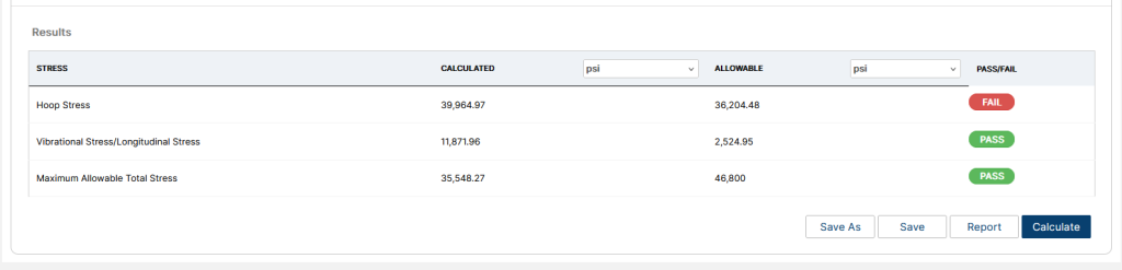
Results
- Calculated and Allowable Hoop Stress( psi)
- Calculated and Allowable Longitudinal Stress (psi)
- Calculated and Allowable Total Stress (psi)
References
- Robert B. Francini, William Nik Baltz – Blasting and Construction Vibrations Near Existing Pipelines: What Are Appropriate Levels, IPC2008-64325.
- California Department of Transportation – Transportation- and construction-induced vibration guidance manual.
- ASME B31.4 – Pipeline Transportation Systems for Liquids and Slurries
- API 5L, API 5LS and API 5LX – Specification of Pipe Grade
- ASTM – Various – Weld Joint Factor
FAQ
-
How do I find the rated energy of my vibratory equipment?
For vibratory rollers, large bulldozers, caisson drilling, jackhammers, and crack-and-seat operations, a rated energy is not necessary.
For pile drivers and hydraulic breakers, the rated energy is often listed in the device specifications from the manufacturer. On the chance it is not listed, however, you can calculate the rated energy using the formula below:
 E_\text{equip} = \frac{P_\text{equip} (\text{hp}) \times 33000 \left( \frac{\text{lb-ft/min}}{\text{hp}} \right)} {f_\text{equip}(\text{vpm})}
Where Pequip is the horsepower of the device, and fequip is the device frequency.