
Introduction
The Weymouth equation is one of the older equations but is still widely used for distribution and gathering systems. It was originally developed from data taken on small, low to medium pressure pipelines.
When it is used for larger, high-pressure pipelines it is quite conservative, as it predicts values for Q which could be 8-12% low for gas transmission through long pipelines, the Weymouth equation is not recommended. The Weymouth equation is typically used for flow conditions:D>6″,\,Pressure\,\,\,1.5psi\,\,< P_1 < \,\,300psi \~\F=C_fD^{0.1667}
D>6",\,Pressure\,\,\,1.5psi\,\,< P_1 < \,\,300psi \\~\\F=C_fD^{0.1667}𝐹 − Transmission Factor
𝐶𝑓 − 11.18
𝐷 − Internal Diameter (in)
Q=C_Q(\frac{T_b}{P_b})D^{2.667}\biggr[ \frac{P_1^2-e^sP_2^2}{GT_fL_eZ} \biggr]^{0.5}
Q=C_Q(\frac{T_b}{P_b})D^{2.667}\biggr[ \frac{P_1^2-e^sP_2^2}{GT_fL_eZ} \biggr]^{0.5}𝑄 − Flow Rate (FT3/day)
𝐶𝑄 − 433.49
𝑇𝑏 − Temperature Base (°R)
𝑃𝑏 − Pressure Base (psia)
𝐷 − Internal Diameter (in)
𝑃1 − Upstream Pressure (psia)
𝑃2 − Downstream Pressure (psia)
𝐺 − Gas Specific Gravity
𝑍 − Compressibility Factor
𝐿𝑒 − Pipe Segment Length including Expansion (mi)
𝑇𝑓 − Gas Flowing Temperature (°R)
s=\frac{C_S\triangle HG}{T_fZ}
s=\frac{C_S\triangle HG}{T_fZ}𝑠 − Elevation adjustment parameter
𝐶𝑆 − 0.0375
𝑍 − Compressibility Factor
𝑇𝑓 − Gas Flowing Temperature (°R)
∆𝐻𝐺 − Change in Elevation (ft)
L_e=\frac{(e^s-1)}{s}
L_e=\frac{(e^s-1)}{s}𝐿𝑒 − Pipe Segment Length including Expansion (mi)
𝑠 − Elevation adjustment parameter
V=0.75\frac{Q_h}{D^2P_{avg}}
V=0.75\frac{Q_h}{D^2P_{avg}}𝑉 − Velocity (ft/sec)
𝑄ℎ − Volumetric flow rate (scf/hr)
𝐷 − Internal Diameter (in)
For Small Pressure Drop P2 > 0.8 P1:
P_{avg}=\frac{(P_1-P_2)}{2}
P_{avg}=\frac{(P_1-P_2)}{2}For Large Pressure Drop:
P_{avg}=\frac{2}{3}\biggr[ P_1+P_2-\frac{P_1P_1}{P_1+P_2} \biggr]
P_{avg}=\frac{2}{3}\biggr[ P_1+P_2-\frac{P_1P_1}{P_1+P_2} \biggr]Case Guide
Part 1: Create Case
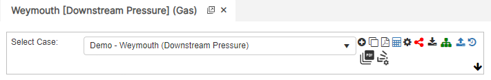
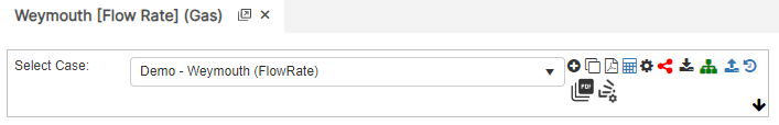
- Select the Weymouth application in the Hydraulics module.
- To create a new case, click the “Add Case” button.
- Enter Case Name, Location, Date and any necessary notes.
- Fill out all required parameters.
- Make sure the values you are inputting are in the correct units.
- Click the CALCULATE button to overview results
Input Parameter
- Temperature base(°F)
- Pressure base(psia)
- Gas Flowing Temperature(°F)
- Gas Specific Gravity
- Compressibility Factor
- Pipeline Efficiency Factor
- Upstream Pressure(psig)
- Downstream Pressure(psig)
- Flow Rate(MSCFH)
- Internal Pipe Diameter(in)
- Length of Pipeline(mi)
- Upstream Elevation(ft)
- Downstream Elevation(ft)
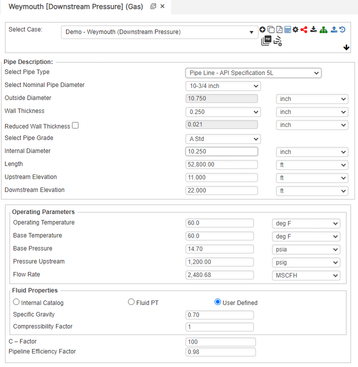
Downstream Pressure
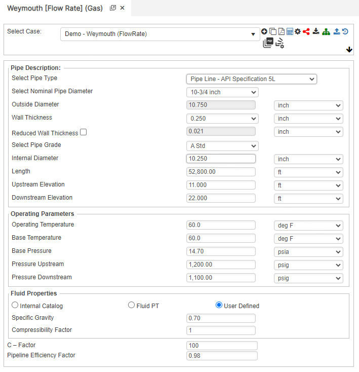
Flow Rate
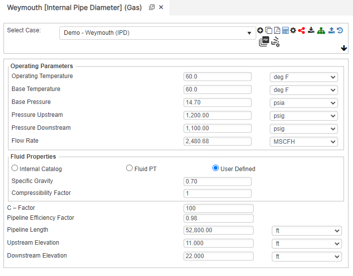
Internal Pipe Diameter
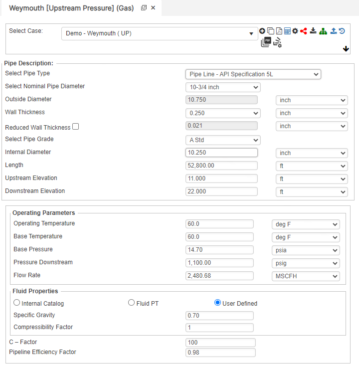
Upstream Pressure
Part 2: Outputs/Reports
- If you need to modify an input parameter, click the CALCULATE button after the change.
- To SAVE, fill out all required case details then click the SAVE button.
- To rename an existing file, click the SAVE As button. Provide all case info then click SAVE.
- To generate a REPORT, click the REPORT button.
- The user may export the Case/Report by clicking the Export to Excel icon.
- To delete a case, click the DELETE icon near the top of the widget.
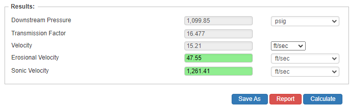
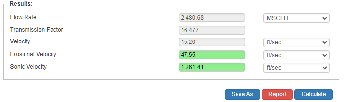
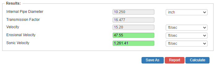
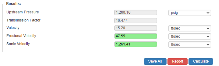
Results
- Downstream Pressure(psig)
- Flow Rate(MCFD)
- Internal Pipe Diameter(in)
- Upstream Pressure(psig)
- Transmission Factor
- Velocity(ft/sec.)
- Erosional Velocity(ft/sec.)
- Sonic Velocity(ft/sec.)
Downstream Pressure
Flow Rate
Internal Pipe Diameter
Upstream Pressure
References
- McAllister, E. W., “Pipeline Rules of Thumb” Gulf Professional Publishing, Seventh Edition
- Menon, Shahi E., “Gas Pipeline Hydraulics”, Systek Technologies, Inc.
- Carroll, Landon and Hudkins, Weston R., “Advanced Pipeline Design”
- American Gas Association (AGA), “Reference: Eq-17-18, Section 17, GPSA”, Engineering Data Book, Eleventh Edition
FAQ
-
Gas Purging Calculations?
Purging is a process of removing gas from the pipeline. Controlled purging of gases from pipelines by direct displacement with other gases that have been safely practiced for many years with the recognition that some flammable mixture is present. Purging of gases from pipelines by direct displacement with another gas also has been similarly practiced. It works both ways; however, there will always be an atmosphere of type of a mixture. This is due to the densities of the gases. Check Out
-
What is Erosional Velocity?
Pipe erosion begins when velocity exceeds the value of C/SQRT(ρ) in ft/s, where ρ = gas density (in lb./ft3) and C = empirical constant (in lb./s/ft2) (starting erosional velocity). We used C=100 as API RP 14E (1984). However, this value can be changed based on the internal conditions of the pipeline. Check Out
-
What is Sonic Velocity?
The maximum possible velocity of a compressible fluid in a pipe is called sonic velocity. Oilfield liquids are semi-compressible, due to dissolved gases. Check Out