
Angled Grid Explosive Charge
The pipe stress and ground motion are a method that would yield reasonable stress estimates by simplifying this source into an equivalent parallel line or point source.
Prediction methods developed are general enough to provide reasonable stress estimates over a wide range of scaled parameters. Some exceptions to the general procedures will exist as a result of explosive geometric configurations i.e. 90 degrees.
Minimum distance from the pipeline to the nearest explosive charge must be greater than two times outside pipe diameter.
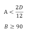
Maximum allowable angle between pipe and explosive line must be less than 90˚
𝐴 − Distance from the Charge to the Pipeline(ft)
𝑅 − Equivalent Standoff Distance(ft)
𝐵 − Angle Between Pipe and Grid,deg., convert to Radians=𝐵(0.0175)
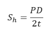
𝑃 − MAOP − Maximum Allowable Operating Pressure(psi)
𝐷 − Pipeline Outside Diameter(in)
𝑡 − Pipe Wall Thickness(in)
𝑆ℎ − Hoop Stress(psi)
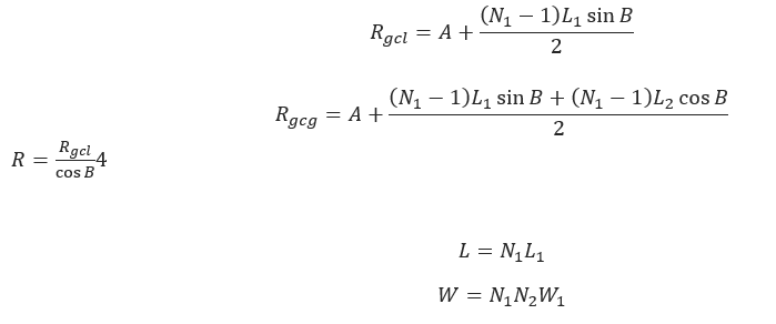
𝐿 − Total Length of Explosive Line(ft)
𝐿1 − Spacing Length Between Charges in Explosive Line(ft)
𝑊 − Total Charge Weight(lbs)
𝑊1 − Weight of Single Charge(lbs)
𝑁1 − Number of Charges in Explosive Line
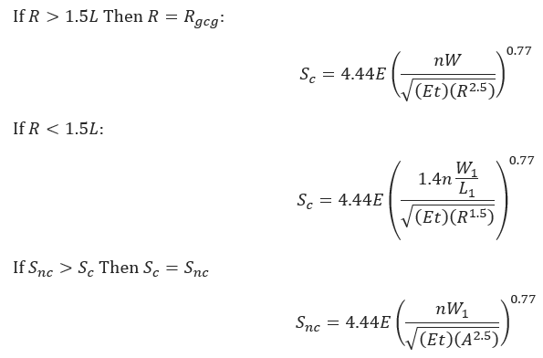
𝑆𝑐 − Maximum Circumferential = 𝑆𝑙 − Maximum Longitudinal Stress(psi)
𝑛 − Equivalent Energy Release Ratio
𝑊 − Weight of Single Charge(lbs)
𝐸 − Modulus of Elasticity
𝑡 − Pipe Wall Thickness(in)
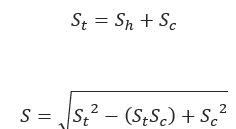
𝑆𝑡 − Combined Hoop and Circumferential Stress(psi)
Blasting Conditions for combined Stress Level
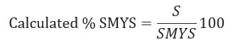
𝐶𝑎𝑙𝑆𝑀𝑌𝑆>%𝑆𝑀𝑌𝑆−NOT ACCEPTABLE/𝐶𝑎𝑙𝑆𝑀𝑌𝑆<%𝑆𝑀𝑌𝑆−ACCEPTABLE
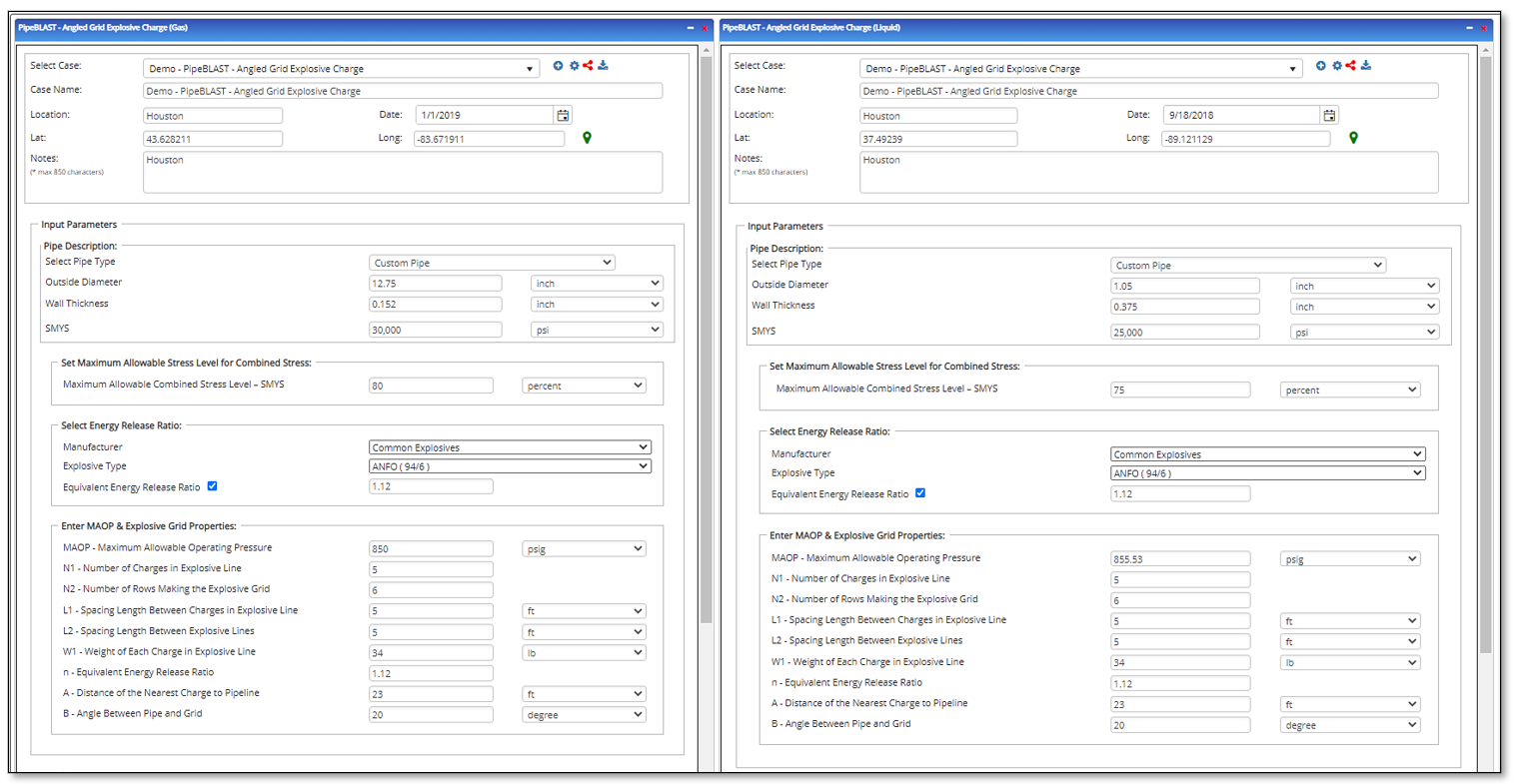
Input Parameters
- To create a new case, click the “Add Case” button
- Select the Angled Grid Explosive Charge application from the Pipe Blast module.
- Enter Case Name, Location, Date and any necessary notes.
- Fill out all required fields.
- Make sure the values you are inputting are in the correct units.
- Click the CALCULATE button.
- Pipe Outside Diameter
- Pipe Wall Thickness
- Specified Minimum Yield Strength
- Maximum Allowable Combined Stress Level – SMYS
- Manufacturer
- Explosive Type
- Equivalent energy release ratio
- MAOP – Maximum Allowable Operating Pressure
- N1 – Number of Charges in Front Row of Explosive Grid
- N2 – Number of Rows Making the Explosive Grid
- L1 – Spacing Length Between Charges in Explosive Line
- L2 – Spacing Length Between Explosive Lines
- W1 – Weight of Single Charge
- n – Equivalent Energy Release Ratio
- A – Distance of the Nearest Charge to Pipeline
- B – Angle Between Pipe and Grid
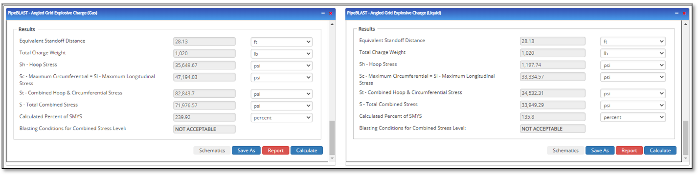
Outputs/Reports
- View the results.
- If an input parameter needs to be edited be sure to hit the CALCULATE button after the change.
- To SAVE, fill out all required case details then click the SAVE button.
- To rename an existing file, click the SAVE As button. Provide all case info then click SAVE.
- To generate a REPORT, click the REPORT button.
- The user may export the Case/Report by clicking the Export to Excel/PowerPoint icon.
- To delete a case, click the DELETE icon near the top of the widget.
- Equivalent Standoff Distance
- Total Charge Weight
- Sh – Hoop Stress
- Sc-Maximum Circumferential = Sl-Maximum Longitudinal Stress
- St – Combined Hoop && Circumferential Stress
- S – Total Combined Stress
- Calculated Percent of SMYS
- Blasting Conditions for Combined Stress Level:
Related Links
Table of Contents
Table of Pages
- Pipeline HUB User Resources
- AC Mitigation PowerTool
- API Inspector's Toolbox
- Crossings Workflow
- Horizontal Directional Drilling PowerTool
- Hydrotest PowerTool
- Pipeline Toolbox
- PRCI AC Mitigation Toolbox
- PRCI RSTRENG
- RSTRENG+
- Ad-hoc Analysis
- Database Import
- Data Availability Dashboard
- ESRI Map
- Report Builder
- Crossings Workflow
- Hydrotest PowerTool
- Investigative Dig PowerTool
- Hydraulics PowerTool
- External Corrosion Direct Assessment Procedure - RSTRENG
- Canvas
- Definitions