
Panhandle A equation is used in the design of large high pressure, long transmission pipelines. The Panhandle A equation was originally developed from Reynolds numbers in the range of:
![]()
The average pipeline efficiency factor of 0.92 normally used in this Panhandle A equation was obtained from actual empirical experience with the metered gas flow rates corrected to standard conditions. The Panhandle A equation provides a reasonable approximation for partially turbulent flow; however, for fully turbulent flow, the Panhandle A equation is not realistic. In the fully turbulent region, the Panhandle B equation is recommended. Pipeline efficiency factors used in the Panhandle equations should be reduced for smaller pipe diameters. For large diameter lines, the efficiency factor may be as high as 0.98.
These Panhandle A and B equations suffer from the substitution of a fixed gas viscosity value into the Reynolds number expression, which, in turn, substituted into the flow equation, results in an expression with a preconditioned bias.
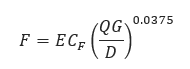
𝐹 − Transmission Factor
E – Pipeline Efficiency Factor
𝐶𝑓 − 7.2111
𝑄 − Flow Rate (FT3/day)
𝐺 − Gas Specific Gravity
𝐷 − Internal Diameter (in)
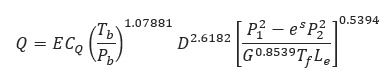
𝑄 − Flow Rate (FT3/day)
E – Pipeline Efficiency Factor
𝐶𝑄 − 435.87
𝑇𝑏 − Temperature Base (°R)
𝑃𝑏 − Pressure Base (psi)
𝐷 − Internal Diameter (in)
𝑃1 − Upstream Pressure (psi)
𝑃2 − Downstream Pressure (psi)
𝐺 − Gas Specific Gravity
𝐿𝑒 − Pipe Segment Length including Expansion (mi)
𝑇𝑓 − Gas Flowing Temperature (°R)
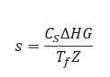
𝑠 − Elevation adjustment parameter
𝐶𝑆 − 0.0375
𝑍 − Compressibility Factor
𝑇𝑓 − Gas Flowing Temperature (°R)
∆𝐻𝐺 − Change in Elevation (ft)
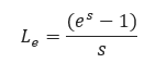
𝐿𝑒 − Pipe Segment Length including Expansion (mi)
𝑠 − Elevation adjustment parameter
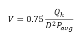
𝑉 − Velocity (ft/sec)
𝑄ℎ − Volumetric flow rate (scf/hr)
𝐷 − Internal Diameter (in)
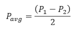
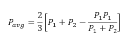
𝑃𝑎𝑣𝑔 − Average Pipeline Pressure (psia)
𝐅𝐨𝐫 𝐬𝐦𝐚𝐥𝐥 𝐩𝐫𝐞𝐬𝐬𝐮𝐫𝐞 𝐝𝐫𝐨𝐩 𝑷𝟐 > 𝟎.𝟖𝑷𝟏:
𝐅𝐨𝐫 𝐥𝐚𝐫𝐠𝐞 𝐩𝐫𝐞𝐬𝐬𝐮𝐫𝐞 𝐝𝐫𝐨𝐩:
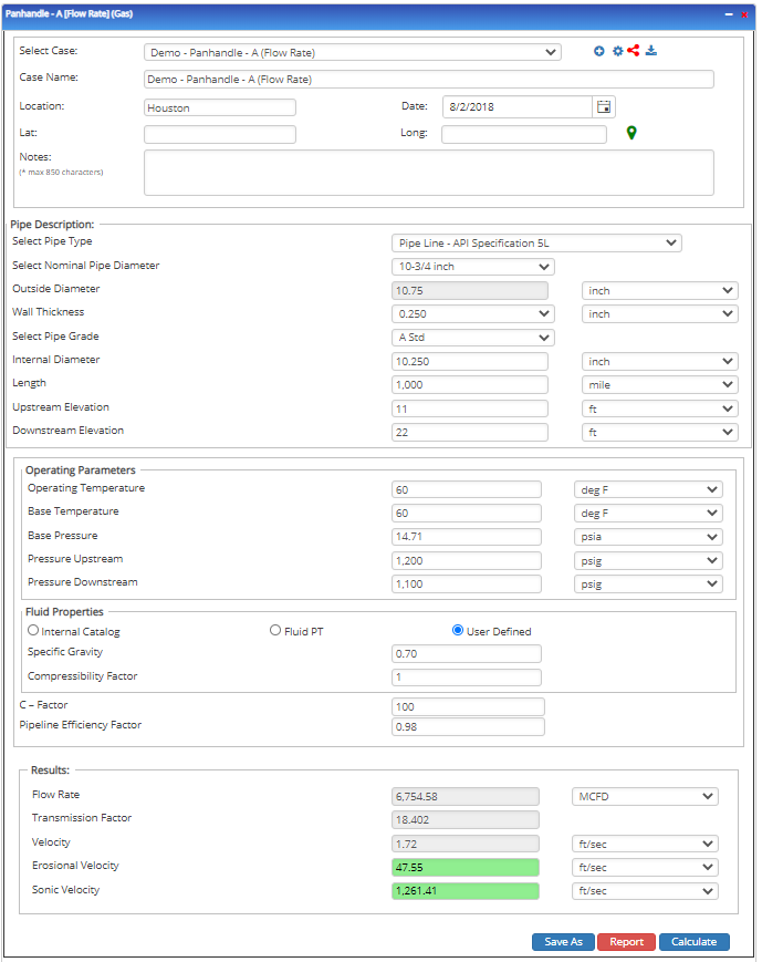
Input Parameters
- To create a new case, click the “Add Case” button
- Select the Unknown and desired Flow Equation
- Enter Case Name, Location, Date, and any necessary notes
- Fill out all required fields.
Make sure the values you are inputting are in the correct units - Click the CALCULATE button.
- Temperature base(°F)
- Pressure base(psia)
- Gas Flowing Temperature(°F)
- Gas Specific Gravity
- Compressibility Factor
- Pipeline Efficiency Factor
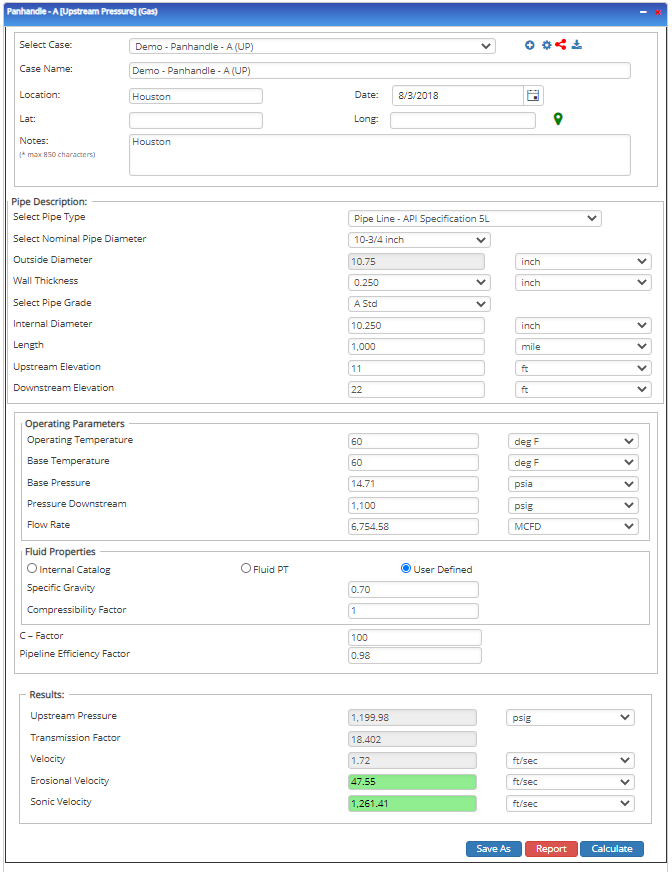
- Upstream Pressure(psig)
- Flow Rate(MCFD)
- Internal Pipe Diameter(in)
- Length of Pipeline(mi)
- Upstream Elevation(ft)
- Downstream Elevation(ft)
Outputs/Reports
- View the results
- If an input parameter needs to be edited be sure to hit the CALCULATE button after the change
- To SAVE, fill out all required case details then click the SAVE button.
To rename an existing file, click the SAVE As button. Provide all case info then click SAVE - To generate a REPORT, click the REPORT button
- The user may export the Case/Report by clicking the Export to Excel/PowerPoint icon.
- To delete a case, click the DELETE icon near the top of the widget
- Flow Rate(ft/sec.)
- Transmission Factor
- Velocity(ft/sec.)
- Upstream Pressure(psi)
- Transmission Factor
- Velocity(ft/sec.)
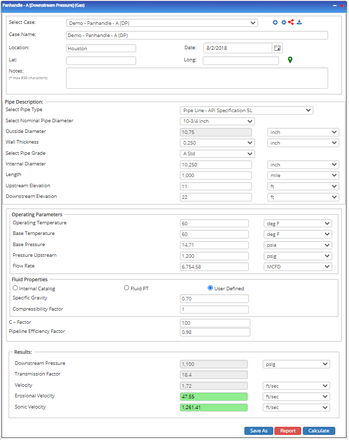
- Downstream Pressure(psi)
- Transmission Factor
- Velocity(ft/sec.)
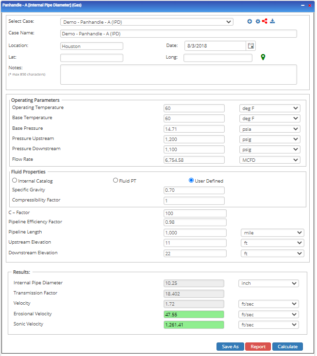
- Internal Pipe Diameter(in)
- Transmission Factor
- Velocity(ft/sec.)
- Erosional Velocity
- Sonic Velocity
Flow Rate
Upstream Pressure
Downstream Pressure
Internal Pipe Diameter
Tutorial Videos
Leveraging a Defined Fluid in PLTB (60 sec)