
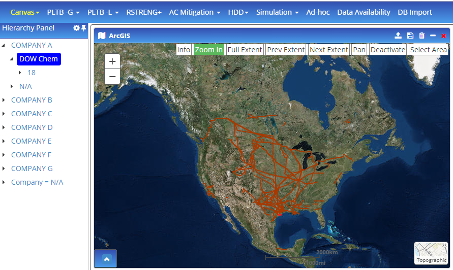
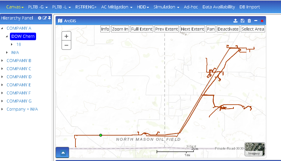
Click on Map from the Application Navigation tab to open the map widget on the canvas.
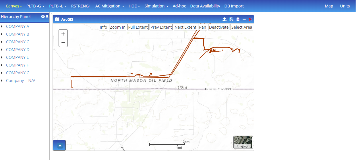
Import
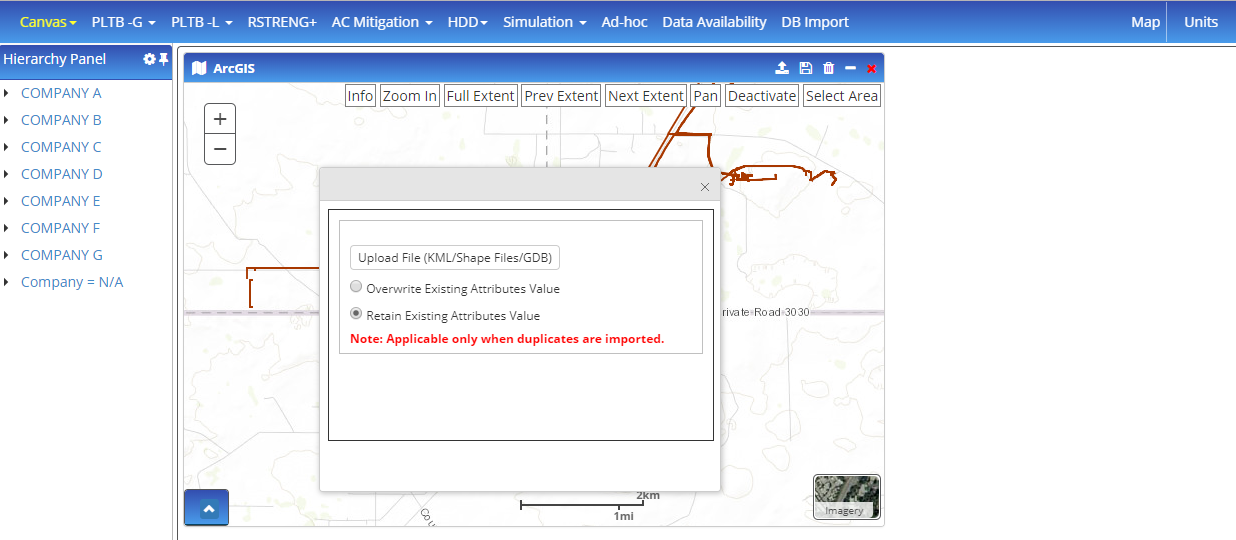
a. Click on the import icon from the map widget which opens a pop-up to upload files. The user can upload the following files:
- Gdb (geo-database)
- shapefile
- kml/kmz file
The user will have to select any of the following options for every file that will be imported:
- Overwrite Existing Attributes Value – so that no duplicates are created for the same data
- Retain Existing Attributes Value – User decides whether to import the file with the changes or to retain the existing values for the same database file
- When the user selects any of the above files, a UI mapping screen opens. This allows the user to map entities from the file. When entities are mapped, the user will have to map the attributes for every entity (by clicking on the red arrows). The application has a built-in smart algorithm to auto-map common parameters. The user can either accept this mapping or change to the desired mapping
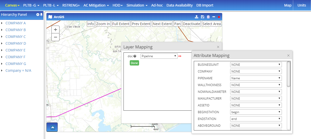
- The user has options to either over-write existing attribute values if the same file is uploaded again or retain existing attribute values and import data for any new entities and attributes in the file imported
Hierarchy Panel Options
When the user selects any options from the hierarchy pane, the following is expected:
- Zooms into the selected entity in such a way that there is about 10% left on all 4 sides of the map.
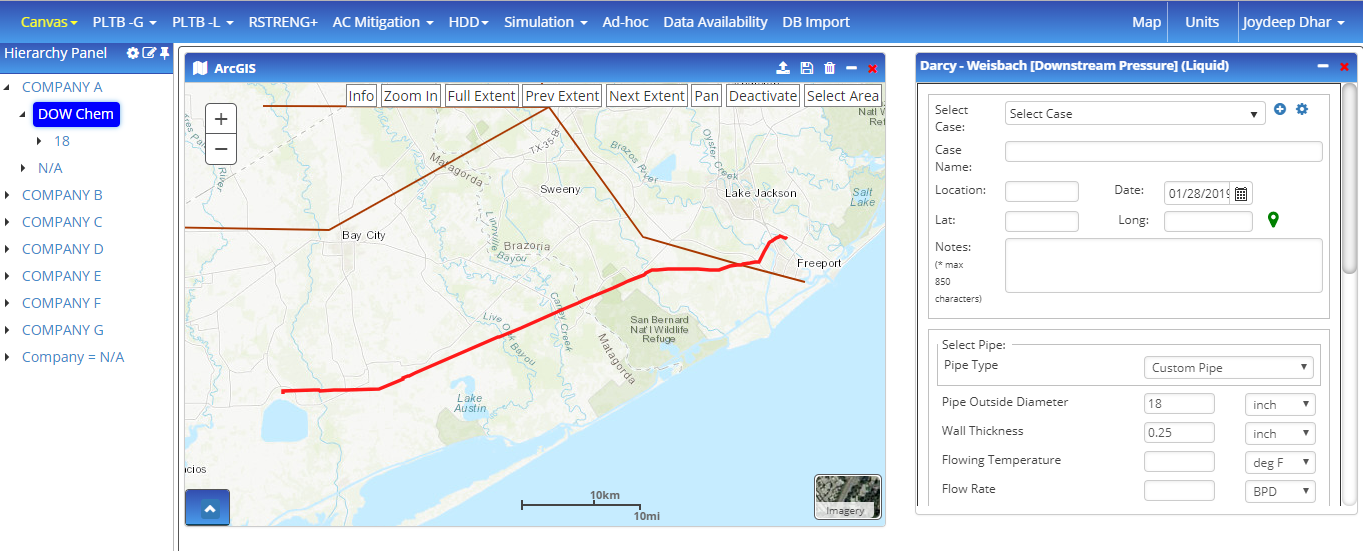
- When a case is selected from the hierarchy pane, the module is launched with the selected case. Cases are filtered to the elements selected.
- When the user selects multiple options from the hierarchy panel (select while holding control key; shift key and select is not an option), all selections are highlighted on the map.
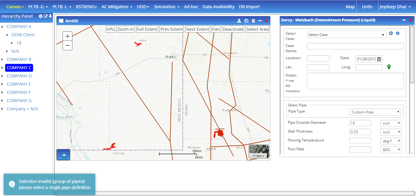
A warning message is generated when a pipeline with more than one pipe definition is selected with a different pipe outside diameter, wall thickness, etc. while a calculation widget is open because the widget cannot load attributes data for all pipes and only one pipe must be selected for creating a case.
- If the user selects a specific pipe on the hierarchy pane, only cases subject to the selected pipe will be available in the case dropdown.
- The user can hold Ctrl and click on the selected entity to de-select single or multiple entities (the most common way of multi-select is to hit control and select the entity on the map. To de-select, click on the entity again while holding down control). Note that the shift key is not supported in making multiple selections.
Note: if an incorrect selection is made in the hierarchy while modules are open, the message generated is “selection invalid (group of pipes)! please select a single pipe definition”
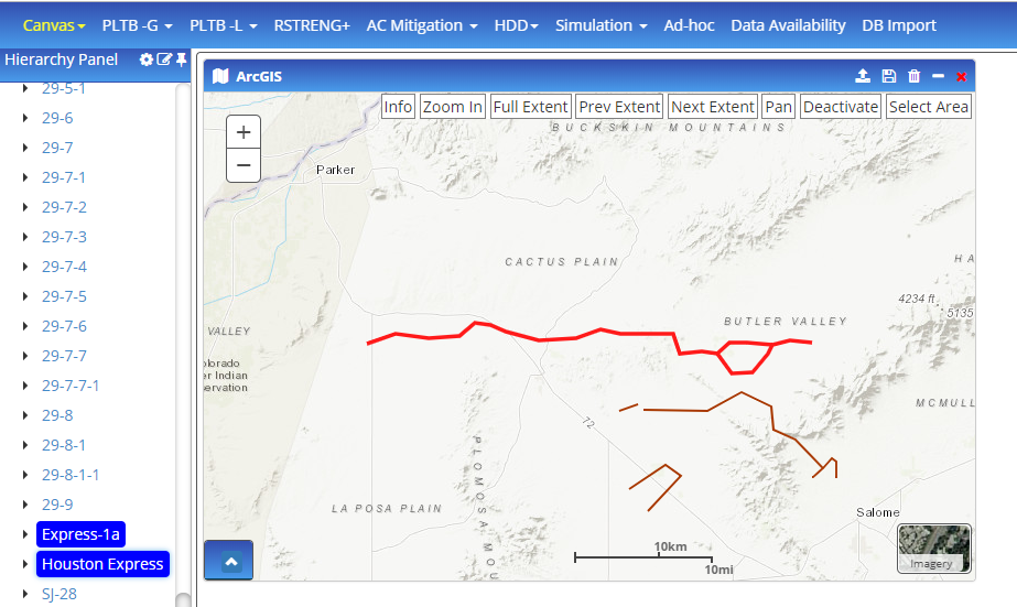
Selection on Map
When making selections on map, the following is expected:
- Zooms into the selected entity in such a way that there is about 10% left on all 4 sides of the map.
- The element selected in the map is highlighted/selected in the hierarchy.
- When a specific module or case of the element is selected, the module is launched with the selected case or the first case in the module selected. Cases are filtered to the elements selected.
- When selection is made, there must be a way to de-select one or many
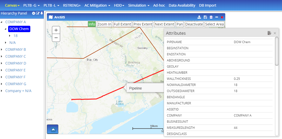
Info Button
- When the info button is clicked, and an entity is selected, it is highlighted/selected in the map and the attributes table for the selected entity opens up.
- When any other option on the map is selected, the info feature will be disabled similar to zoom in.
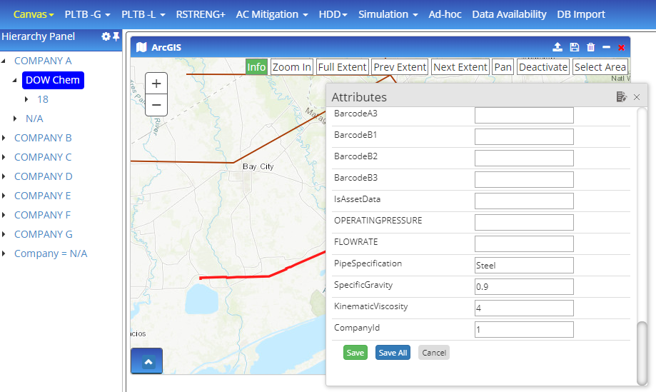
- The user can click on info, followed by selecting an entity where the attributes show up. These attributes can be edited if the user has the Map editor license from Technical Toolboxes.
Zoom Options
- Zoom in will allow the user to zoom into the selected area.
- Selecting any other option disables the zoom-in option
Full Extent
- Full extent will display the earth’s complete extent.
Previous Extent
- The previous extent will take you to the previous map screen that was viewed (works as back and forward options of a browser)
Next Extent
Next Extent will take you to the screen before the previous extent was clicked (works as back and forward options of a browser)
Pan
Pan enables the user to move the map in any direction
Deactivate
Deactivate disables all map selection and works similar to the pan option
Select Area
Select Area is used to multi-select multiple layers such as pipes, valves, pumps, compressors, roads, transmission lines, etc.
- Entities selected from Select Area must be selected/highlighted in the hierarchy.
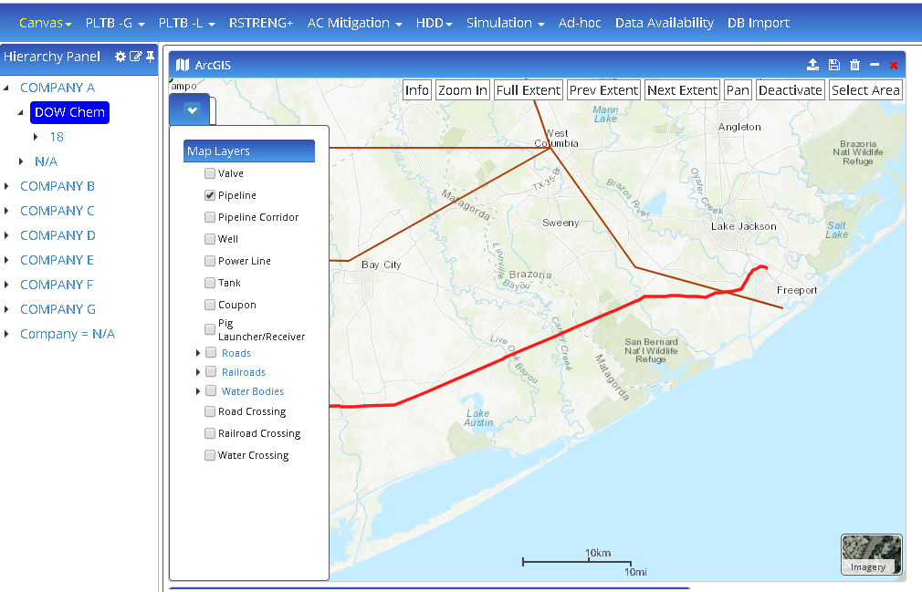
List Arrows
The arrow at the bottom is the list of layers that can be viewed on the map.
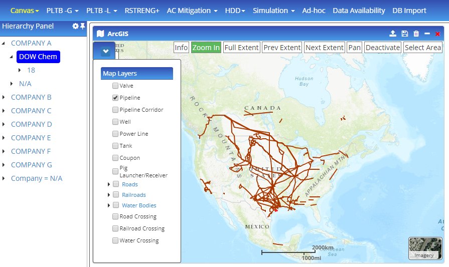
- By default only pipes will be checked and if the users want to add any additional layers, they are free to do so.
Satellite View
- Satellite View allows the option to change views between satellite and map.
- Import button allows the user to import gdb, shapefiles, and kml/kmz files into the map.
- The import can be a batch or continuous process where multiple files can be imported.
- Once the file is imported, the user will have to map the layers followed by attribute mapping as described in point 2 with image.
- The content of the imported file is displayed in the map widget for QC purposes but has not yet been written to the project database or saved for later use.
- The save button saves all the imports and any modifications to new/existing entities displayed on the map.
- The user can select either single/multiple entities (from map and hierarchy) or area select (using select area) and from the map and click the delete icon to delete selected entities

From the feature map service, the user can click on Add New Entity where the user is allowed to add/draw the following:
- Pipelines
- Transmission lines
- Valves
- Compressors
- Pumps
- Wells
- Pipeline corridor
- Roads (line feature)
- Water bodies (polygon feature and line feature)
- Railways (line feature)
- Pipe-road crossing (point intersection)
- Pipe – railway crossing (point intersection)
- Pipe – water (point intersection)
- Pipe – water (polygon intersection)
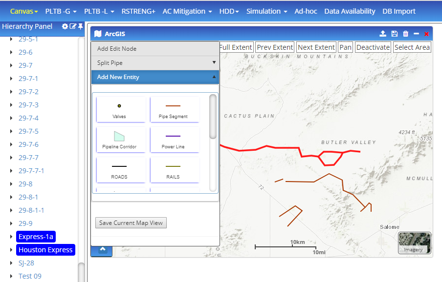
The procedure to do so will be by clicking on the selection and then clicking on the map where you want to create a new entity. When done, add edit node allows the user to add multiple nodes and pseudo nodes for the following:
- Change the orientation of the existing pipeline/power line
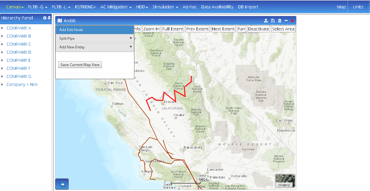
- Click on the Map icon to the left of ArcGIS in the Map header
- Select “Add Edit Node” from the available options
- Now double click on the pipeline/transmission line that you want to add edit node
- The dark/big points are the nodes while the light/small points are pseudo-nodes
- You can move the pseudo-nodes to create a new node
- The nodes are moved to change the orientation of the pipeline/power line
- Calculate angle for AC Mitigation
- Allows the user to calculate angles between the sections (drawn using feature map service) and the pipelines and transmission lines
Road Crossing
Select an area by drawing a polygon and click on Road Crossing. The application gives 2 options to the user, the first being “find crossing”, which is the point feature and shows the point of intersection and the second is “find intersection with buffer” where the pipe is buffered and the line feature of the intersection is calculated and displayed.
The above crossings can be calculated for primary, secondary, and/or minor roads. Similarly, only pipes and roads of interest can be manually selected by the user and crossing can be calculated:
- Click on save to save the crossings layer to the database
- Crossing QC can be accessed while clicking on the info button followed by selecting the road crossing and then clicking on edit. The Map/Data Accuracy tab allows the user to make necessary QC changes to the crossing
- Real crossing, shapefile accurate – This will be selected by default for every crossing identified or entered
- Real crossing, shapefile inaccurate – if the crossing location is incorrect due to an incorrect shapefile, the user can mark the identified crossing as incorrect and enter the correct location of the crossing.
- Not a crossing, shapefile inaccurate – if a crossing was identified, the user can mark the crossing as not a crossing
- Real crossing, the road not mapped – if a crossing exists but the shapefile does not represent a road, the user can select the crossing and specify that the road is not mapped yet
- Real crossing, no road – the user can add a crossing when there is no road shapefile
Railroad Crossing
Select an area by drawing a polygon and click on a railroad crossing. The application gives 2 options to the user, the first being “find crossing”, which is the point feature and shows the point of intersection and the second is “find intersection with buffer” where the pipe is buffered and the line feature of the intersection is calculated and displayed. The above crossings can be calculated for multi-line and/or double line railroads
Similarly, only pipes and railroads of interest can be manually selected by the user and crossing can be calculated:
- Click on save to save the crossings layer to the database
- Crossing QC can be accessed while clicking on the info button followed by selecting the railroad road crossing and then clicking on edit. The Map/Data Accuracy tab allows the user to make necessary QC changes to the crossing
- Real crossing, shapefile accurate – This will be selected by default for every crossing identified or entered
- Real crossing, shapefile inaccurate – if the crossing location is incorrect due to an incorrect shapefile, the user can mark the identified crossing as incorrect and enter the correct location of the crossing.
- Not a crossing, shapefile inaccurate – if a crossing was identified, the user can mark the crossing as not a crossing
- Real crossing, railroad not mapped – if a crossing exists but the shapefile does not represent a railroad, the user can select the crossing and specify that the railroad is not mapped yet
- Real crossing, no railroad – the user can add a crossing when there is no railroad shapefile
Water Crossing
Select an area by drawing a polygon and click on water crossing. The application gives an option to the user to “find crossing”, which can be either a point feature and shows the point of intersection and/or line feature which shows the line of intersecting a polygon. The above crossings can be calculated for all water layer options
Similarly, only pipes and water bodies of interest can be manually selected by the user and crossing can be calculated:
- Click on save to save the crossings layer to the database
- Crossing QC can be accessed while clicking on the info button followed by selecting the water crossing and then clicking on edit. The Map/Data Accuracy tab allows the user to make necessary QC changes to the crossing
- Real crossing, shapefile accurate – This will be selected by default for every crossing identified or entered
- Real crossing, shapefile inaccurate – if the crossing location is incorrect due to an incorrect shapefile, the user can mark the identified crossing as incorrect and enter the correct location of the crossing.
Not a crossing, shapefile inaccurate – if a crossing was identified, the user can mark the crossing as not a crossing
Real crossing, water body not mapped – if a crossing exists but the shapefile does not represent a water body, the user can select the crossing and specify that the water body is not mapped yet
Real crossing, no water body – the user can add a crossing when there is no railroad shapefile
Water Crossing
Select an area by drawing a polygon and click on water crossing. The application gives an option to the user to “find crossing”, which can be either a point feature and shows the point of intersection and/or line feature which shows the line of intersecting a polygon. The above crossings can be calculated for all water layer options.
Similarly, only pipes and water bodies of interest can be manually selected by the user and crossing can be calculated:
- Click on save to save the crossings layer to the database
Crossing QC can be accessed while clicking on the info button followed by selecting the water crossing and then clicking on edit. The Map/Data Accuracy tab allows the user to make necessary QC changes to the crossing.- Real crossing, shapefile accurate – This will be selected by default for every crossing identified or entered.
- Real crossing, shapefile inaccurate – if the crossing location is incorrect due to an incorrect shapefile, the user can mark the identified crossing as incorrect and enter the correct location of the crossing.
- Not a crossing, shapefile inaccurate – if a crossing was identified, the user can mark the crossing as not a crossing.
- Real crossing, water body not mapped – if a crossing exists but the shapefile does not represent a water body, the user can select the crossing and specify that the water body is not mapped yet.
- Real crossing, no water body – the user can add a crossing when there is no water shapefile.
Perpendicular Distance
Buffer Service
The user can select a layer (all available layers within the application) and enter a buffer distance that the user wants to see on the map. The user can either select a layer, single/multiple entities based on drawing a polygon and buffer the selected region:
- Click on save to save the crossings layer to the database.
Dynamic Segmentation
- Locate Distance Markers
- Measure Events
- Identify Location
- Click on Identify Location and select point on pipe, gives the route/pipe id and the to measure or distance at which the point was selected.
- Point Location From Measure
- Enter the route/pipe id and enter the measure or from measure and now click on identify location – gives a point on the pipe id with the from measure distance.
Line Location
Network Service
The accordion button to the bottom left expands to select the map layer when clicked. The selected map layers will be displayed on the map.
- On clicking, the marked arrow in the image above opens the layers, and clicking the arrow again will close it.
Limitations
The current version of the ESRI Map KML/KMZ import feature on the Hub does not support KML/KMZ files with multiple layers. Users must ensure that the KML/KMZ file used contains only a single layer. A future release will include the capability to support the import of KML/KMZ layer groups.
Videos
- Video Guide to importing entities into ArcGIS and then into other tools (6:41)
Related Links
Table of Contents
Table of Pages
- Pipeline HUB User Resources
- AC Mitigation PowerTool
- API Inspectors Toolbox
- Horizontal Directional Drilling PowerTool
- Crossings Workflow
- Pipeline Toolbox
- Encroachment Manager
- PRCI AC Mitigation Toolbox
- PRCI Thermal Analysis for Hot-Tap Welding
- PRCI River-X
- PRCI RSTRENG
- RSTRENG+
- Ad-hoc Analysis
- Database Import
- Data Availability Dashboard
- ESRI Map
- Report Builder
- Hydrotest PowerTool
- Investigative Dig PowerTool
- Hydraulics PowerTool
- External Corrosion Direct Assessment Procedure - RSTRENG
- Canvas
- Definitions
- Pipe Schedule and Specifications Tables