
Specific Radius of Curvature
This procedure is for designing the bore path specific using radius of curvature calculations for plastic pipe that are basically the same as discussed for steel pipe. As with steel product pipe, plastic pipe, when installed by HDD, may experience high-tension loads, severe bending, and external fluid pressures. HDD installation subjects the pipe to axial tensile forces caused by the frictional drag between the pipe and the borehole or drilling fluid, the frictional drag on the ground surface, the capstan effect around drill-path bends, and hydrokinetic drag. The pipe may also be subjected to external hoop pressures caused by the external fluid head and bending stresses. Determination of pullback forces involves the assumption of many variables and installation techniques that include:
Pipe Weight:
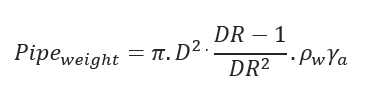
Pipe weight – Weight of the pipe (lbs/ft)
D – Pipe Outside Diameter (inch)
DR – Diameter Ratio (D/t)
𝜌𝑤 = Density of water (lb/ft3)
𝛾𝑎 = Specific gravity of pipe material
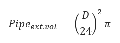
Pipe Exterior Volume:
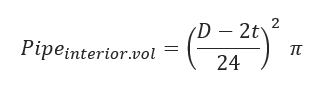
Pipe Interior Volume:
Weight of Water in pipe:
(to be calculated only if the pipe is filled with water)
𝑊𝑎𝑡𝑒𝑟𝑃•𝑤𝑒𝑖𝑔ℎ𝑡 = 𝑃𝑖𝑝𝑒𝑖𝑛𝑡𝑒𝑟𝑖𝑜𝑟•𝑣𝑜𝑙 ∗𝑊𝑤𝑒𝑖𝑔ℎ𝑡
Wweight – Weight of water (lb/ft3)
Displaced Mud Weight:
𝐷𝑖𝑠𝑝𝑙𝑎𝑐𝑒𝑚𝑢𝑑𝑊𝑒𝑖𝑔ℎ𝑡 = 𝑃𝑖𝑝𝑒𝑒𝑥𝑡.𝑣𝑜𝑙 𝑚𝑢𝑑𝑤𝑡
mudwt = Weight of mud (lb/ft3)
Effective Weight of Pipe:
𝑤𝑎 = 1.06 𝑃𝑖𝑝𝑒𝑤𝑒𝑖𝑔ℎ𝑡
𝑊𝑆 = 𝑤𝑎 + 𝑊𝑎𝑡𝑒𝑟𝑃•𝑤𝑒𝑖𝑔ℎ𝑡 − 𝐷𝑖𝑠𝑝𝑙𝑎𝑐𝑒𝑚𝑢𝑑𝑊𝑒𝑖𝑔ℎ𝑡
Hydrokinetic Force:
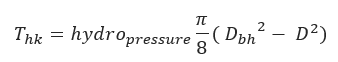
Thk = hydro kinetic force (lbs)
Dbh = Borehole diameter, usually 1.5.D (inch)
Straight section A-B
Friction from Soil:
𝑓𝑟𝑖𝑐2 = 𝑊𝑆𝐿1𝑐𝑜𝑠𝜃𝑆1𝜇𝑆𝑜𝑖𝑙
L1 – Length of the straight section 1
θS1 – Angle in degrees from horizontal for straight section 1
μSoil – Average coefficient of friction between pipe and soil. Recommended value between .21-.3 (Maidla)
Drag Forces from Mud:
𝐷𝑟𝑎𝑔2 = 𝜋𝐷𝐿1𝜇𝑚𝑢𝑑
μmud – Fluid drag coefficient for steel tube pulled through bentonite mud
Tension on Section:
∆𝑇2 = |𝑓𝑟𝑖𝑐2| + 𝐷𝑟𝑎𝑔2 − 𝑊𝑠𝐿1𝑠𝑖𝑛𝜃𝑠1 + 𝑇ℎ𝑘
Cumulative Pull Load:
𝑇2 = ∆𝑇2 + 𝑇1
T1 – Pull back as the pipe enters the drill hole (lbf)
Curved Section B-C
(based on Roark’s solution for elastic beam deflection)
θC1 – Angle in degrees from horizontal for curved section 1
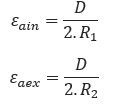
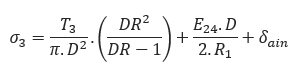
R1- Radius of curvature of curve section 1 (ft)
Larc1 – Length of curved section 1(ft)
E – Young’s Modulus (psi)
Friction from Soil:
𝑓𝑟𝑖𝑐 = |𝑁3𝜇𝑆𝑜𝑖𝑙|
Drag Forces from Mud:
𝐷𝑟𝑎𝑔3 = 𝜋𝐷𝐿𝑎𝑟𝑐1𝜇𝑚𝑢𝑑
Tension on Section:
Cumulative Pull Load:
𝑇3 = ∆𝑇3 + 𝑇2
Straight Section C-D
Friction from Soil:
𝑓𝑟𝑖𝑐4 = 𝑊𝑆𝐿𝑠𝑐𝑜𝑠𝜃𝑆𝜇𝑆𝑜𝑖𝑙
Ls – Length of straight section between bends (ft)
θs – – Angle in degrees from horizontal for straight sections between bends
Drag Forces from Mud:
𝐷𝑟𝑎𝑔4 = 𝜋𝐷𝐿𝑠𝜇𝑚𝑢𝑑
Tension on Section:
∆𝑇4 = |𝑓𝑟𝑖𝑐4| +𝐷𝑟𝑎𝑔4 – 𝑊𝑠𝐿𝑠𝑠𝑖𝑛𝜃𝑠 + 𝑇ℎ𝑘
Cumulative Pull Load:
𝑇4 = ∆𝑇4 + 𝑇3
Curved Section D-E
θC2 – Angle in degrees from horizontal for curved section 2
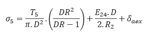
R2– Radius of curvature of curve section 2 (ft)
Larc2 – Length of curved section 2(ft)
Friction from Soil:
𝑓𝑟𝑖𝑐 = |𝑁5𝜇𝑆𝑜𝑖𝑙|
Drag Forces from Mud:
𝐷𝑟𝑎𝑔5 = 𝜋𝐷𝐿𝑎𝑟𝑐2𝜇𝑚𝑢𝑑
Tension on Section:
Cumulative Pull Load:
𝑇5 = ∆𝑇5 + 𝑇4
Straight Section E-F
Friction from Soil:
𝑓𝑟𝑖𝑐6 = 𝑊𝑆𝐿2𝑐𝑜𝑠𝜃𝑆2𝜇𝑆𝑜𝑖𝑙
Drag Forces from Mud:
𝐷𝑟𝑎𝑔6 = 𝜋𝐷𝐿2𝜇𝑚𝑢𝑑
Tension on Section:
∆𝑇6 = |𝑓𝑟𝑖𝑐6| + 𝐷𝑟𝑎𝑔6 – 𝑊𝑠𝐿1𝑠𝑖𝑛𝜃𝑠12 – Length of the straight section 2
θS2 – Angle in degrees from horizontal for straight section 2
Cumulative Pull Load:
𝑇6 = ∆𝑇6 + 𝑇5
Total pull load of the pipe:
𝑇𝑡𝑜𝑡𝑎𝑙 = ∆𝑇2 + ∆𝑇3 + ∆𝑇4 + ∆𝑇5 + ∆𝑇6
Ttotal – Total pull load of the pipe (lbf)
Bending Strain:
R = 40 D
Bending Stress:
𝛿𝑎𝑖𝑛 = 𝐸24.𝜀𝑎𝑖𝑛
𝛿𝑎𝑒𝑥 = 𝐸24.𝜀𝑎𝑒𝑥
E24 = 24 hr-Apparent Modulus of Elasticity (psi)
Allowable Tensile Stress:
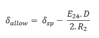
δsp – Allowable/Safe Pull Stress (psi)
Tensile Stress at Point A:
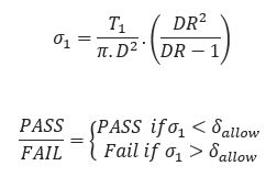
Tensile Stress at Point B:
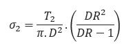
Tensile Stress at Point C:
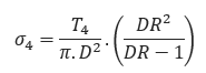
Tensile Stress at Point D:
Tensile Stress at Point E:
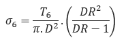
Tensile Stress at Point F:
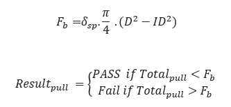
Breakaway Links Settings:
Static Head Pressure:
𝑃𝑒𝑥𝑡 = 𝜌𝑤•𝛾𝑏•𝐻
H = depth of the bore profile (ft), usually the depth of the horizontal section
Maximum Pressure During Pull back
𝑃𝑚𝑎𝑥 = 𝑃𝑒𝑥𝑡 + ℎ𝑦𝑑𝑟𝑜𝑝𝑟𝑒𝑠𝑠𝑢𝑟𝑒
Ovality Compensation Factor:
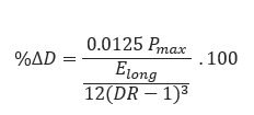
Buoyant Deformation:
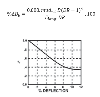
f0 – Ovality compensation factor based on % of Deflection
Tensile Reduction Factor:
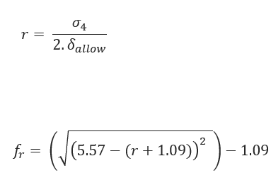
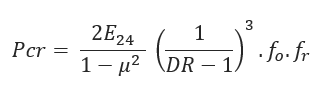
Critical Collapse Pressure:
Safety Factor:
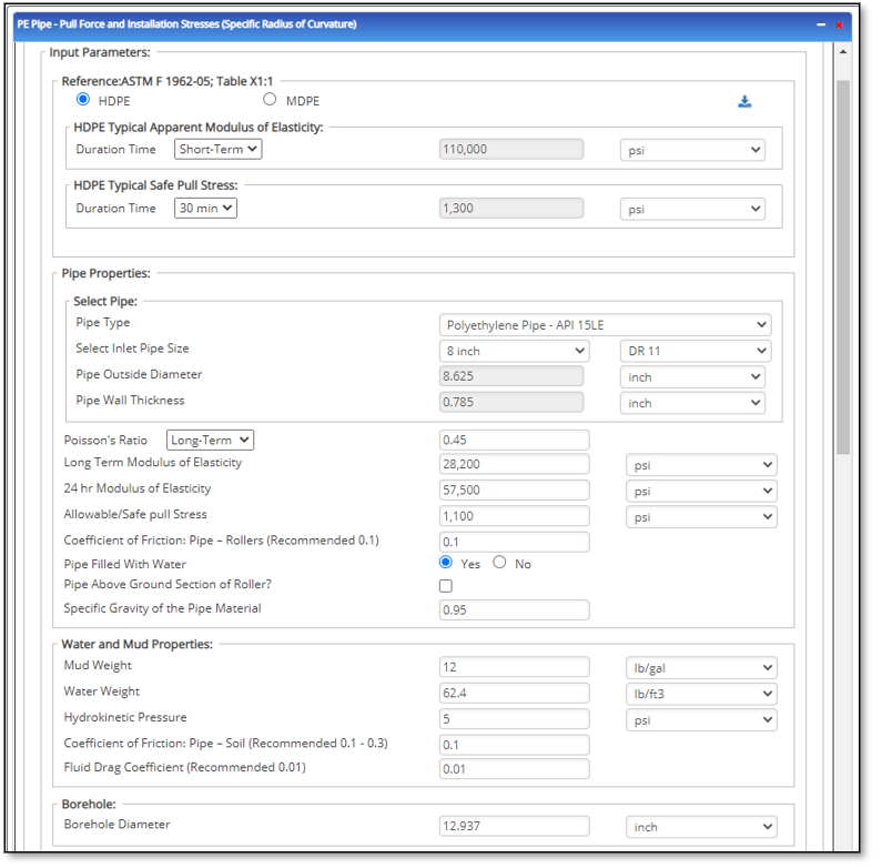
Input Parameters
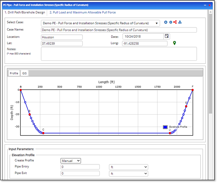
Elevation Profile:
- Create Profile
- Pipe Entry
- Pipe Exit
Drill Path/Borehole Design: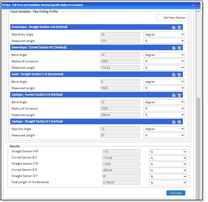
- Downslope: Straight Section A – B (Vertical)
- Pipe Entry Angle A – B [degree]
- Measured Length [ft]
- Downslope:
Curved Section B – C (Vertical)- Bend Angle B – C [degree]
- Radius of Curvature B – C [ft]
- Measured Length [ft]
- Straight Section C – D (Horizontal)
- Horizontal Angle[degree]
- Measured Length [ft]
- Upslope: Curved Section D – E (Vertical)
- Radius of Curvature D – E
- Measured Length [ft]
- Upslope: Straight Section E – F (Vertical)
- Pipe Exit Angle[degree]
- Measured Length [ft]
*The design changes based on borehole design (section configuration)
Pipe Properties:
- Pipe Type
- Select Inlet Pipe Size (in)
- Pipe Outside Diameter (in)
- Pipe Wall Thickness(in)
- Standard Dimension Ratio (DR)
- Long Term Modulus of Elasticity (psi)
- Poisson’s Ratio
- 24 hr. Modulus of Elasticity
- Allowable Safe Pull Stress (psi)
- Coefficient of Friction: Pipe – Rollers (0.1)
- Pipe Filled with Water (Y/N
- Pipe Above Ground Section of Roller (Check Box)
- Angle of pipe Above Ground on Roller (°)
- Pipe Section Above Ground on Roller (ft.)
- Specific Gravity of Pipe Material
Water and Mud Properties:
- Mud Weight (lbs./gal)
- Water Weight(lbs./ft3)
- Hydrokinetic Pressure
- Coefficient of Friction: Pipe – Soil (0.1 – 3)
- Fluid Drag Coefficient (Recommended (0.01)
Borehole:
- Borehole Diameter (in)
Outputs/Reports
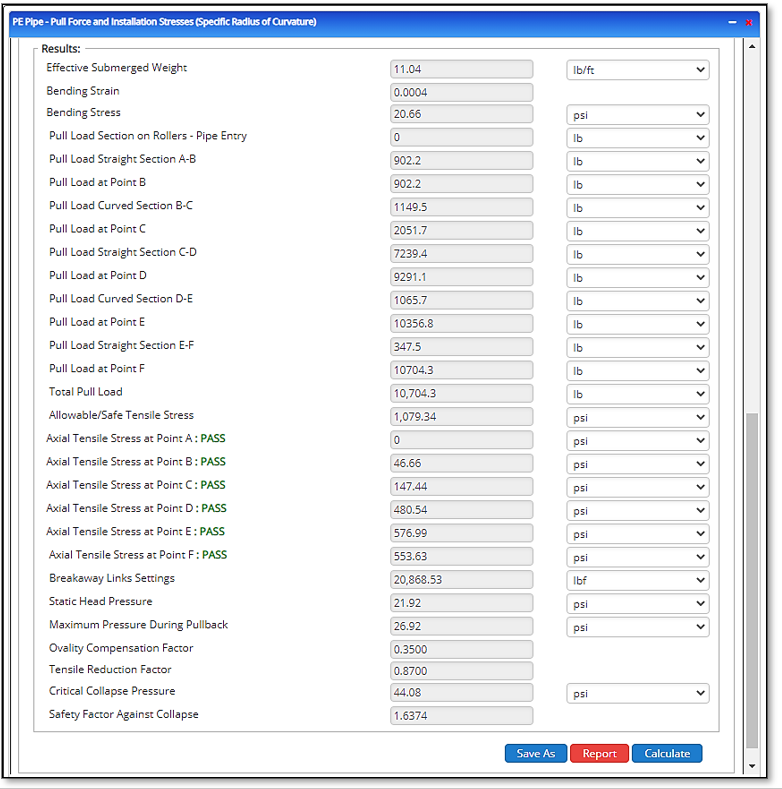
Results:
- Effective Submerged Weight
- Bending Strain
- Bending Stress
- Pull Load Section on Rollers – Pipe Entry
- Pull Load Straight Section A-B
- Pull Load at Point B
- Pull Load Curved Section B-C
- Pull Load at Point C
- Pull Load Straight Section C-D
- Pull Load at Point D
- Pull Load Curved Section D-E
- Pull Load at Point E
- Pull Load Straight Section E-F
- Pull Load at Point F
- Total Pull Load
- Allowable/Safe Tensile Stress
- Axial Tensile Stress at Point A: PASS
- Axial Tensile Stress at Point B: PASS
- Axial Tensile Stress at Point C: PASS
- Axial Tensile Stress at Point D: PASS
- Axial Tensile Stress at Point E: PASS
- Tensile Stress at Point F: PASS
- Breakaway Links Settings
- Static Head Pressure
- Maximum Pressure During Pullback
- Ovality Compensation Factor
- Tensile Reduction Factor
- Critical Collapse Pressure
- Safety Factor Against Collapse