
Accidental Release From Liquid Hydrocarbon Pipeline
Introduction
The Pipeline Toolbox is home to many tools and calculators. The PLTB User’s Guide presents information, guidelines and procedures for use during design, construction, operations and integrity tasks for field or office applications.
Although transmission pipelines are generally considered the safest and most economical way of carrying large quantities of dangerous substances (flammables, explosives and/or toxics), they can constitute a potential threat of major accidents. The impact on man and the environment of a potential major accident associated with pipelines should therefore be fully assessed for the characterization and adoption of appropriate preventive and/or mitigation measures, aimed at protecting people and the environment in their proximity. In case of liquid hydrocarbons carried by pipelines, the risk for the surroundings is due to the possibility of the content release with resulting land contamination, other than risk of fire and explosions.
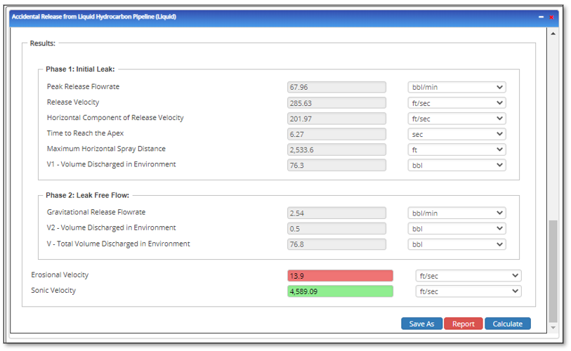
Erosional Velocity
Pipe erosion begins when velocity exceeds the value of C/SQRT(ρ) in ft/sec, where ρ = gas density (in lb./ft3) and C = empirical constant (in lb/s/ft2) (starting erosional velocity). We used C=100 as API RP 14E (1984). However, this value can be changed based on the internal conditions of the pipeline. The following equation is used for the calculation.
Inputs
- C – Factor (dimensionless)
- Compressibility Factor (dimensionless)
- Gas Gravity (dimensionless)
- Operating Pressure (psig)
- Operating Temperature (deg F)
Erosional Velocity is in ft/sec.
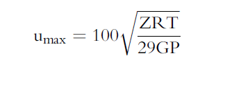
Sonic Velocity
The maximum possible velocity of compressible fluid gas/liquids in pipe is called sonic velocity.
Inputs
-
- K = Cp/Cv – the ratio of specific heats at constant pressure to constant volume (fluid directive)
- G=32.2 ft/sec
- R=1544/mol. Wt.
- T = Absolute temperature in deg R
K = A + B(P) – C(T)1/2 – D(API) – E(API)2 + F(T) (API)
Sonic Velocity is in ft/sec.
Accidental Release From Liquid Hydrocarbon Pipeline
Accidental release from liquid pipeline volumes are calculated based on the leak rate and time to isolate pipeline section and release rate during free flow. Gravitational effects are the sole mechanism for release after isolation siphoning effects, drain down procedures, and pipeline depressurization and are not considered in this calculation.
PHASE 1: The discharge/release rate of liquid through the sharp-edged orifice can be calculated as:
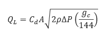
𝑄𝐿 − Liquid Discharge/Release Rate[lb/sec]
𝐶𝑑 − Discharge Coefficient = 0.62
𝐴 − Hole Cross Sectional Area[ft2]
𝑔𝑐 − Gravitational Conversion Factor 32.2[ft/sec2]
∆𝑃 − Pressure Differential[psi]
𝜌 − Specific Weight of Liquid [lb/ft2]
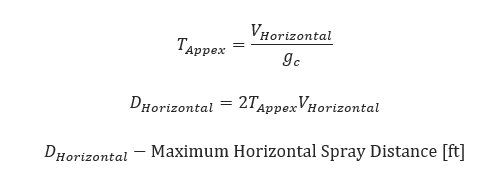
Calculation of Spray Zone
𝑉𝐻𝑜𝑟𝑖𝑧𝑜𝑛𝑡𝑎𝑙 = 𝑉 cos 𝜃
𝑉𝐻𝑜𝑟𝑖𝑧𝑜𝑛𝑡𝑎𝑙 − Velocity Horizontal Component[ft/sec]
𝜃 − Angle of Release ,°.for furthest possible radius θ = 45
𝑉 − Calculated Release Velocity[ft/sec]
PHASE 2: Pressure differential during free flow phase:
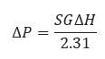
∆𝑃 − Pressure Differential [psi]
𝑆𝐺 − Specific Gravity
∆𝐻 − Elevation Differential [ft]
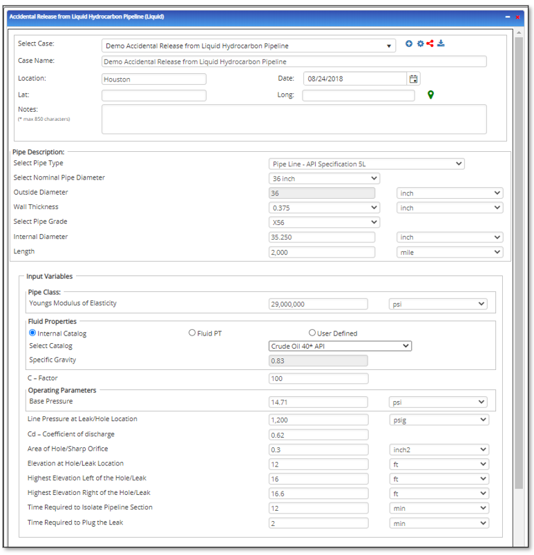
Input Parameters
- To create a new case, click the “Add Case” button
- Select the Accidental Release from Liquid Hydrocarbon Pipeline application in the AGR & GPRA module.
- Enter Case Name, Location, Date, and any necessary notes.
- Fill out all required fields.
- Make sure the values you are inputting are in the correct units.
- Click the CALCULATE button.
- Specific Gravity
- Pipe Type
- Nominal Pipe Size[in]
- Wall Thickness[in]
- Outside Diameter[in]
- Atmospheric Pressure[psia]
- Line Pressure at Hole/Leak Location [psig]
- Cd – Coefficient of Discharge
- Internal Pipe Diameter [in]
- Area of Hole/Sharp Orifice
- Length of Pipeline Section[mi]
- Elevation at Hole/Leak Location [ft]
- Highest Elevation Left of the Hole/Leak [ft]
- Highest Elevation Right of the Hole/Leak [ft]
- Time Required to Isolate Pipeline Section [min]
- Time Required to Plug the Leak [min]
Outputs/Reports
- View the results.
- If an input parameter needs to be edited be sure to hit the CALCULATE button after the change.
- To SAVE, fill out all required case details then click the SAVE button.
- To rename an existing file, click the SAVE As button. Provide all case info then click SAVE.
- To generate a REPORT, click the REPORT button.
- The user may export the Case/Report by clicking the Export to Excel/PowerPoint icon.
- To delete a case, click the DELETE icon near the top of the widget.
PHASE 1: INTAKE LEAK PHASE
- Peak Release Flowrate [bbl/min]
- Release Velocity [ft/sec]
- Horizontal Component of Release Velocity [ft/sec]
- Time to Reach the Apex [sec]
- Maximum Horizontal Spray Distance [ft]
- V1-Volume Discharged in Environment [bbls]
PHASE 2: LEAK FREE-FLOW PHASE
- Gravitational Release Flowrate {bbl/min]
- V2-Volume Discharged in Environment [bbls]
- V-Total Volume Discharged in Environment [bbls]
References
-
Handbook of Chemical Hazard Analysis Procedures,
-
Risk Management Program Guidance for Offsite Consequence
-
API Recommended Practice 520, Sizing, Selection, and Installation of Pressure-Relieving Devices in Refineries, Part I, American Petroleum Institute,
-
API Recommended Practice 521, Guide for Pressure-Relieving and Depressuring Systems, American Petroleum Institute,
-
Crane Limited, Flow of Fluids through Valves, Fittings, and Pipe, Technical Paper No. 410-C, Crane Engineering Division
-
The Netherlands Organization of Applied Scientific Research. Methods for the Calculation of Physical Effects, CPR 14E: Part (TNO Yellow Book), Bosch, C.J.H. van den and N.J. Duijm,
-
Discharge Rate Calculation Methods or Use in Plant Safety Assessments, Safety and Reliability, Ramskill, P.K.
Related Links
Table of Contents
Table of Pages
Table of Contents
- Pipeline HUB User Resources
- AC Mitigation PowerTool
- API Inspector's Toolbox
- Horizontal Directional Drilling PowerTool
- Crossings Workflow
- Hydrotest PowerTool
- Pipeline Toolbox
- Encroachment Manager
- PRCI AC Mitigation Toolbox
- PRCI RSTRENG
- RSTRENG+
- Ad-hoc Analysis
- Database Import
- Data Availability Dashboard
- ESRI Map
- Report Builder
- Crossings Workflow
- Hydrotest PowerTool
- Investigative Dig PowerTool
- Hydraulics PowerTool
- External Corrosion Direct Assessment Procedure - RSTRENG
- Canvas
- Definitions
- Pipe Schedule and Specifications Tables