Accidental Gas Release Through a Small Hole in Pipeline
The Pipeline Toolbox is home to many tools and calculators. The PLTB User’s Guide presents information, guidelines and procedures for use during operations and integrity tasks for field or office applications.
The evolving demand for oil and natural gas supply along with the efficiency of distributing them by using pipelines over long distances generates need for construction of several pipelines. On the other hand, the need of easements or servitudes to provide the passage of pipelines launches a challenge to pipeline operators to design pipelines to minimize land conflicts and environmental impacts. At the same time, it is necessary to assure the safety of population. The solution to these issues often involves the construction of parallel pipelines along new or existing right-of-way (rows). The underground parallel pipelines escalation or domino effect could occur when two or more pipelines run adjacent to a gas or liquefied pipeline. When it happens, the consequences of the final event are notably greater than the consequences associated with the primary event. Therefore, neglecting the evaluation of the domino effect in the risk assessment of under-ground parallel pipelines can give rise to a risk underestimation.

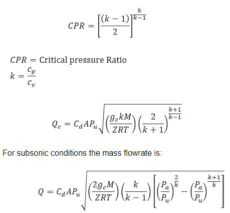
𝑄𝑐 − Mass Flow Rate[lb/sec] Sonic/Chocked Conditions
𝑄 − Mass Flow Rate[lb/sec] Subsonic
𝐶𝑑 − Discharge Coefficient
𝐴 − Discharge Hole Area[ft2]
𝑔𝑐 − Gravitational Conversion Factor 32.2[ft/sec2]
𝑘 − Specific Heat Ratio of Gas
𝑅 − Universal Gas Constant=1545.3[ft∙lb/lb∙mol−°R]
𝑇 − Gas Temperature[°R]
𝑀 − Gas Molecular Weight
𝑃𝑢 − Absolute Source Pressure[lb/ft2]
𝑃𝑎 − Absolute Ambient Pressure[lb/ft2]
𝑍 − Gas Compressibility Factor
For many gases, k ranges from about 1.1 to about 1.4, and so sonic or choked gas flow usually occurs when the source gas pressure is about 25 to 28 PSIA or greater.
Input Parameters
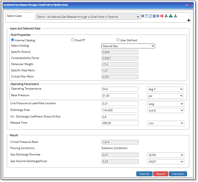
- To create a new case, click the “Add Case” button
- Select the Accidental Gas Release Through a Small Hole in the Pipeline application in the AGR & GPRA module.
- Enter Case Name, Location, Date and any necessary notes.
- Fill out all required fields.
- Make sure the values you are inputting are in the correct units.
- Click the CALCULATE button.
- Atmospheric Pressure
- Gas Temperature
- Line Pressure at the Leak/Hole Location
- Discharge Area
- Cd – Discharge Coefficient – Sharp Orifice
- Molecular Weight of Gas
- Specific Heat Ratio of Gas
- Compressibility Factor of Gas
- Release Time [minutes]
Outputs/Reports
- View the results.
- If an input parameter needs to be edited be sure to hit the CALCULATE button after the change.
- To SAVE, fill out all required case details then click the SAVE button.
- To rename an existing file, click the SAVE As button. Provide all case info then click SAVE.
- To generate a REPORT, click the REPORT button.
- The user may export the Case/Report by clicking the Export to Excel/PowerPoint icon.
- To delete a case, click the DELETE icon near the top of the widget.
- Critical Pressure Ratio
- Flow Condition
- Peak Initial Release Rate – From Single Side
- Effective Release Rate – From Both Sides
- Calculated Tap Diameter(in)

References
- GRI-00/0189, A Model for Sizing High Consequence Areas Associated with Natural Gas Pipelines, Gas Technology Institute
- PHMSA – Final Report TTO Number 13, Delivery Order DTRS56-02-D-70036, Michael Baker Jr., Inc. –
- PHMSA – Final Report TTO Number 14, Delivery Order DTRS56-02-D-70036, , Michael Baker Jr., Inc.
- Crane Limited, Flow of Fluids through Valves, Fittings, and Pipe, Technical Paper No. 410-C, Crane Engineering Division
- Schram, W., “Prediction of Crater Caused by Underground Pipeline Rupture”, N.V. Nederland se Gasunie, Report TR/T 97.R.2515
- NEN 3651, Annex A: “Determining Disturbance Zone Dimension”
- PRCI L51861, “Line Rupture and Spacing of Parallel Lines”, Battelle Memorial Institute
