
Pipeline Compressors
Introduction
The Pipeline Toolbox is home to many tools and calculators. The PLTB User’s Guide presents information, guidelines, and procedures for use during design, construction, and operations tasks for field or office applications.
A compressor station is one of the most critical components in a natural gas pipeline system. Compressor stations supply the energy to pump gas from production fields, to overcome frictional losses in transmission pipelines, and to pump gas into and from storage reservoirs. Careful design and operation of these facilities are vital to maintaining the integrity of the entire pipeline system.
The intent of this module is to provide the entry-level engineer, the resident compressor designer, and other gas industry personnel, particularly those engaged in gas supply projects, with the fundamentals of natural gas compression from the planning through the operating phases.
Erosional and Sonic Velocity has been added to the following Modules and Calculations.
- Compressor Station Piping – Gas Velocity
Erosional Velocity
Pipe erosion begins when velocity exceeds the value of C/SQRT(ρ) in ft/s, where ρ = gas density (in lb./ft3) and C = empirical constant (in lb./s/ft2) (starting erosional velocity). We used C=100 as API RP 14E (1984). However, this value can be changed based on the internal conditions of the pipeline. The following equation is used for the calculation.
Inputs
- C – Factor (dimensionless)
- Compressibility Factor (dimensionless)
- Gas Gravity (dimensionless)
- Operating Pressure (psig)
- Operating Temperature (deg F)
Erosional Velocity is in ft/sec
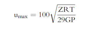
Sonic Velocity
The maximum possible velocity of compressible fluid gas/liquids in pipe is called sonic velocity.
Inputs
-
- K = Cp/Cv – the ratio of specific heats at constant pressure to constant volume (fluid directive)
- G=32.2 ft/sec
- R=1544/mol. Wt.
- T = Absolute temperature in deg R
K = A + B(P) – C(T)1/2 – D(API) – E(API)2 + F(T)(API)
Sonic Velocity is in ft/sec
Module/Application
- Centrifugal Compressor – Adiabatic Head
- Centrifugal Compressor – Required Adiabatic Horsepower
- Centrifugal Compressor – Required Polytrophic Horsepower
- Centrifugal Compressor – Fan Laws
- Reciprocating Compressor – Cylinder/Equivalent Capability & Horsepower
- Compressor Station Piping – Pipe Diameter, Wall Thickness and Gas Velocity
- Local Atmospheric Pressure
References
- Engineering Data Book, Volume 1, Gas Processors Suppliers Association, Tenth Edition
- Compressor Station Operation, Book T-2, GEOP, American Gas Association (A.G.A.)
- Compressor Selection and Sizing, Royce N. Brown, Second Edition, Gulf Professional Publishing
Appendix of Definitions
ABSOLUTE PRESSURE – Gauge pressure plus barometric pressure. Absolute pressure can be zero only in a perfect vacuum.
ADIABATIC OR ISENTROPIC – Adiabatic efficiency is defined as the ratio of work output for an ideal isentropic compression process to the work input to develop the required head.
COMPRESSION RATIO –The quotient obtained from dividing the absolute
discharge pressure by the absolute suction pressure
CAPACITY–The volumetric quantity of gas expressed in MMcf/d (m3/d) or MMscf/d [m3/d (st)] that passes through the compressor unit; capacity is basically a function of compressor geometry, gas
composition, temperature, pressure, and compressor speed.
CENTRIFUGAL COMPRESSOR – This type of compression unit uses a natural gas-fired turbine to turn a centrifugal compressor. The centrifugal compressor is like a large fan inside a case, which pumps the gas as the fan turns. A small portion of natural gas from the pipeline is burned to power the turbine. These can also be powered by electric motors.
CENTRIFUGAL FAN – Centrifugal compressors are also similar to centrifugal fans that increase the flow of energy by increasing the radius of the discharge system.
DISCHARGE PRESSURE–The gas pressure existing on the discharge, or outlet, side of the compressor unit is expressed in lbf/in2 (kPa) gauge or lbf/in2 (kPa) absolute; as with suction pressure, the exact
point of measurement is important in the final sizing and selection of the compressor
HORSEPOWER–The time rate of work that is developed by the prime mover as required by the compressor; the total required horsepower is a function of capacity, compression ratio, and compressor (thermodynamic) efficiency, and mechanical efficiencies of the power transmission system.
RECIPROCATING ENGINE OR COMPRESSOR – Commonly known as “recips,” these engines are fueled by natural gas from the pipeline. Reciprocating pistons, located in cylinder cases on the side of the unit, compress the natural gas. The compressor pistons and the power pistons are connected to a common crankshaft. The advantage of reciprocating compressors is that the volume of gas pushed through the pipeline can be adjusted incrementally to meet small changes in customer demand
SUCTION PRESSURE–The gas pressure existing on the suction, or intake, side of the compressor unit expressed in lbf/in2 (kPa) gauge or lbf/in2 (kPa) absolute. The exact point of measurement of suction
pressure is important in the final sizing and selection of the compressor.
Related Links
Table of Contents
Table of Pages
- Pipeline HUB User Resources
- AC Mitigation PowerTool
- API Inspectors Toolbox
- Horizontal Directional Drilling PowerTool
- Crossings Workflow
- Pipeline Toolbox
- Encroachment Manager
- PRCI AC Mitigation Toolbox
- PRCI Thermal Analysis for Hot-Tap Welding
- PRCI River-X
- PRCI RSTRENG
- RSTRENG+
- Ad-hoc Analysis
- Database Import
- Data Availability Dashboard
- ESRI Map
- Report Builder
- Hydrotest PowerTool
- Investigative Dig PowerTool
- Hydraulics PowerTool
- External Corrosion Direct Assessment Procedure - RSTRENG
- Canvas
- Definitions
- Pipe Schedule and Specifications Tables