
Compressor Station Piping – Pipe Diameter, Wall Thickness and Gas Velocity
This application uses gas velocity and flow rates to determine the minimum required pipe diameter for station piping.
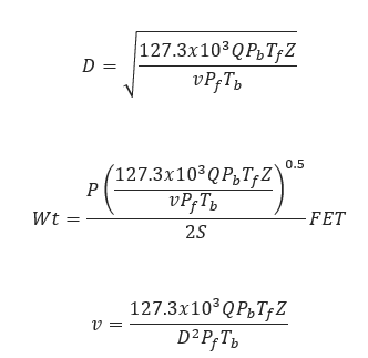
𝑣 − Gas Velocity[ft/min]
𝑄 − Flow Rate[MMCFD]
𝑊𝑡 − Wall Thickness[in]
𝑃 − Design Pressure[psi]
𝐹 − Design Factor
𝐸 − Longitudinal Joint Factor
𝑇 −Temperature Derating Factor
𝑃𝑏 − Base Pressure[psia]
𝑇𝑓 − Flowing Temperature[°R]
𝑍 − Compressibility Factor
𝐷 − Internal Pipe Diameter[in]
𝑃𝑓− Flowing Pressure[psia]
𝑇𝑏 − Base Temperature[°R]
Note: Gas velocity in piping should not exceed 2000(ft/min)
Input Parameters
- To create a new case, click the “Add Case” button
- Select the Compressor Station Piping – Pipe Diameter, Wall Thickness and Gas Velocity application from the Pipeline Compressor module.
- Enter Case Name, Location, Date and any necessary notes.
- Fill out all required fields.
- Make sure the values you are inputting are in the correct units.
- Click the CALCULATE button.
Outputs/Reports
- View the results.
- If an input parameter needs to be edited be sure to hit the CALCULATE button after the change.
- To SAVE, fill out all required case details then click the SAVE button.
- To rename an existing file, click the SAVE As button. Provide all case info then click SAVE.
- To generate a REPORT, click the REPORT button.
- The user may export the Case/Report by clicking the Export to Excel/PowerPoint icon.
- To delete a case, click the DELETE icon near the top of the widget.
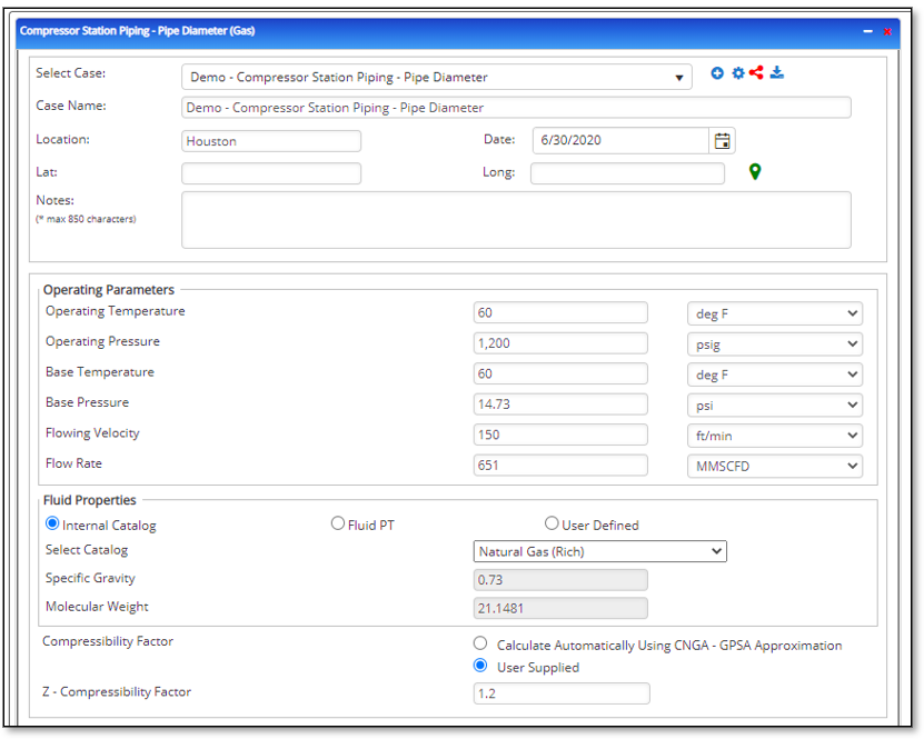
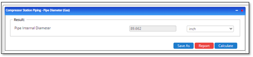
Pipe Diameter
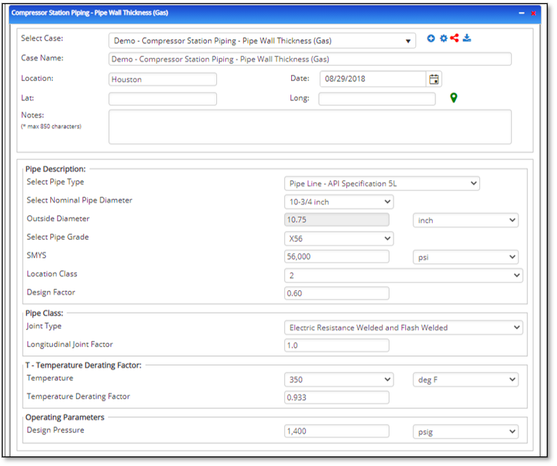
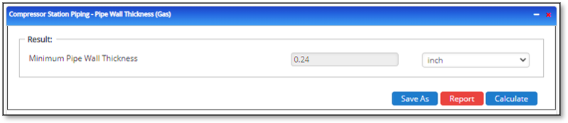
Pipe Wall Thickness
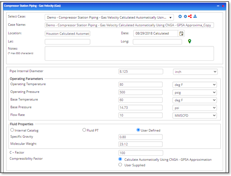
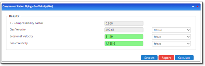
Gas Velocity
Related Links
Table of Contents
Table of Pages
Table of Contents
- Pipeline HUB User Resources
- AC Mitigation PowerTool
- API Inspector's Toolbox
- Horizontal Directional Drilling PowerTool
- Crossings Workflow
- Hydrotest PowerTool
- Pipeline Toolbox
- Encroachment Manager
- PRCI AC Mitigation Toolbox
- PRCI RSTRENG
- RSTRENG+
- Ad-hoc Analysis
- Database Import
- Data Availability Dashboard
- ESRI Map
- Report Builder
- Crossings Workflow
- Hydrotest PowerTool
- Investigative Dig PowerTool
- Hydraulics PowerTool
- External Corrosion Direct Assessment Procedure - RSTRENG
- Canvas
- Definitions
- Pipe Schedule and Specifications Tables