
Introduction
The Pipeline Toolbox is home to many tools and calculators. The PLTB User’s Guide presents information, guidelines and procedures for use during design, construction, operations and integrity tasks for field or office applications.
Analysis and design of buried pipelines are usually based on classical theories and semi-empirical methods. The confidence in these approaches is very limited and use of them could lead to a very conservative design, which could cause major increases in costs. One of such methods is the American Petroleum Institute API recommended practice 1102 to design pipelines which are to be located under highways and railroad crossings.
The Wheel and Track Load Analysis calculations were designed to evaluate the overburden and vehicle loads on buried pipe with a Single Layer System (soil only) or a Double Layer Systems (timbers, pavement and soil). Spangler computed the load transmitted to the pipe due to surface loading using Boussinesq theory for a surface point load or distributed load based on numerical integration.
Gas Piping Technology Guide (GPTC) is a method that is proven and acceptable that can be used in the cases when the crossing conditions for design are out of the scope and the limitations of API RP 1102 and PCPISCES. Examples include depth of cover and 48” diameter pipes.
The CEPA Wheel Load, Track Load, and Grid Load calculations were designed to model the effects of different surface loading scenarios for buried pipelines that allows a variety of vehicle types to be analyzed more accurately because it accounts for the distribution of load from the vehicle, wheel contact, axle weight, etc.. The calculations offered here were developed by report released by Canadian Energy Pipeline Association (CEPA) in October 2009 for “Development of a Pipeline Surface Loading Screening Process and Assessment of Surface Load Dispersing Methods” that was performed by Keifner & Associates, Inc.
Module/Application
-
API 1102 Pipeline Crossing Highway
- Use Case: design road crossings using trenchless methods
- Limitations: applicable to pipes between with depth of cover 3-10 feet
- Differentiator: accounts for fatigue due to cyclic loading
-
API 1102 Pipeline Crossing Railroad
- Use Case: design road and railroad crossings using trenchless methods
- Limitations: applicable to pipes between with depth of cover 3-10 feet
- Differentiator: accounts for fatigue due to cyclic loading
-
Wheel Load Analysis
- Use Case: calculate the overburden and vehicle loads on buried pipe
- Limitations:
- does not account for fatigue due to cyclic loading
- soil load on pipe is assumed that backfill soil slides down without friction, pipe is supported by itself and does not assist in the support
- Differentiator: accounts for Single Layer System (soil only) or Double Layer Systems (timbers/pavement and soil)
-
Track Load Analysis
- Use Case: calculate the overburden and track loads on buried pipe with a Single Layer System (soil only).
- Limitations:
- does not account for fatigue due to cyclic loading
- soil load on pipe is assume that backfill soil slides down without friction, pipe is supported by itself and does not assist in the support
- Differentiator:
-
CEPA Track Load Analysis <page under construction>
- Use Case:
- Special Considerations:
- Limitations:
- Differentiator:
-
CEPA Wheel Load Analysis <page under construction>
- Use Case:
- Special Considerations:
- Limitations:
- Differentiator:
-
CEPA Grid Load Analysis <page under construction>
- Use Case:
- Special Considerations:
- Limitations:
- Differentiator:
-
Design of Uncased Pipeline Crossings
- Use Case: design of Uncased Pipeline Crossings where conditions for design are out of the scope and limitations of API 1102 & PC Pisces.
- Special Considerations:
- total calculated combined stress should not exceed 100% of SMYS (Safety Factor of 1).
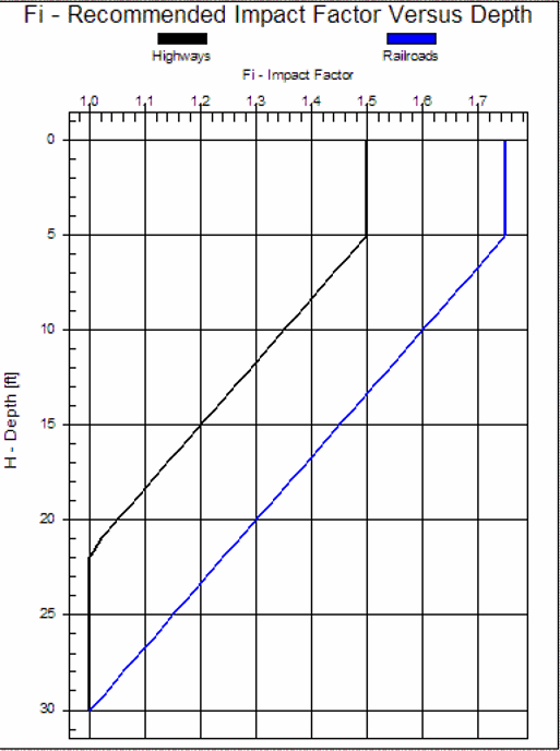
- GPTC Guide sets impact factor at 1.5 for non‐ridged piping.
- Recommend for railroad crossings an impact factor of 1.75.
Tutorial Videos
- Finding Road Crossings (2 min 52 sec)
- Crossings Workflow Demo (4 min 50 sec)
References
-
Battelle Petroleum Technology Report on “Evaluation of Buried Pipe Encroachments” which considered the theoretical work done by M.G. Spangler on overburden and vehicle loads on buried pipe.
-
“Technical Summary and Database for Guidelines for Pipelines Crossing Beneath Railroads and Highways” (GRI-91/0285, Final Report)
-
Cornell/GRI Guidelines are given in “Guidelines for Pipelines Crossing Beneath Highways” (Stewart, et al., 1991b) and “Guidelines for Pipelines Crossing Beneath Highways”.
-
ASME B31.8 “Gas Transmission and Distribution Systems” “Evaluation of Buried Pipe Encroachments”, BATTELLE, Petroleum Technology Center, 1983
-
API RP 1102 – Steel Pipelines Crossing Railroads and Highways
-
CEPA and Keifner & Associates, Inc. report on “Development of a Pipeline Surface Loading Screening Process and Assessment of Surface Load Dispersing Methods (David J. Warman, James D. Hart, Robert B., Francini, 05-44RI, 2009), October 2009
Appendecies
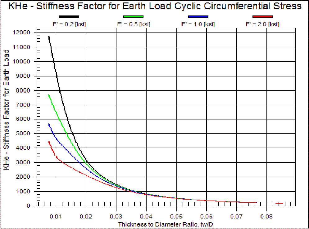
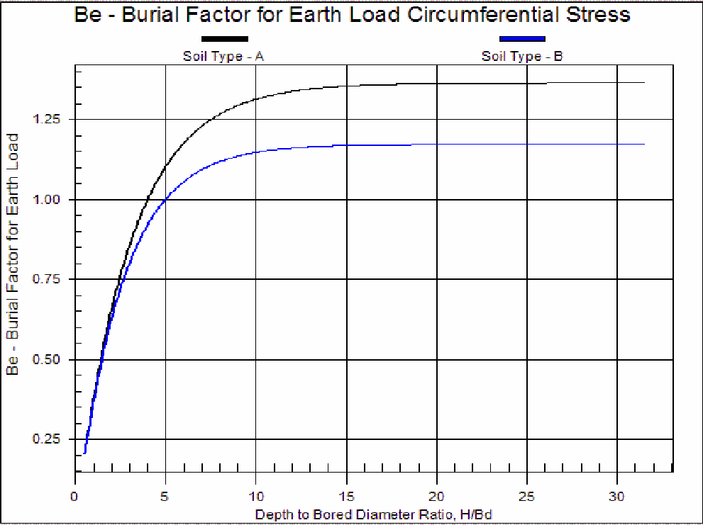
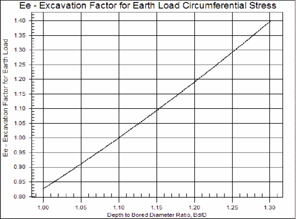
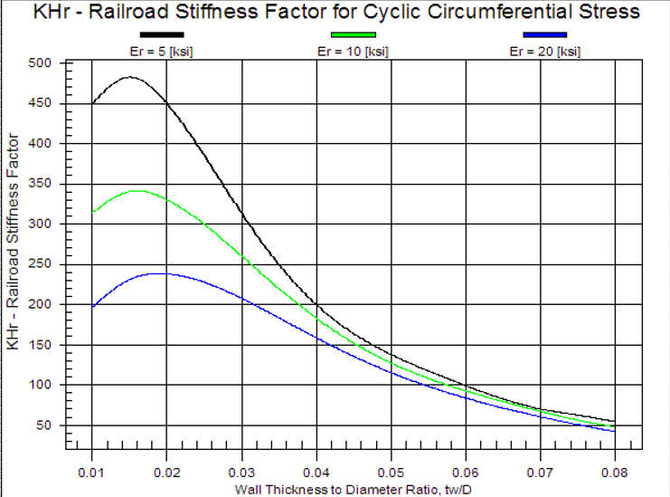
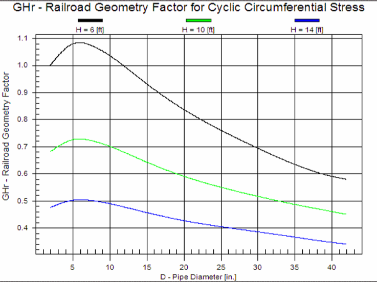
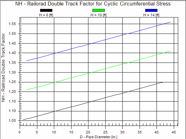
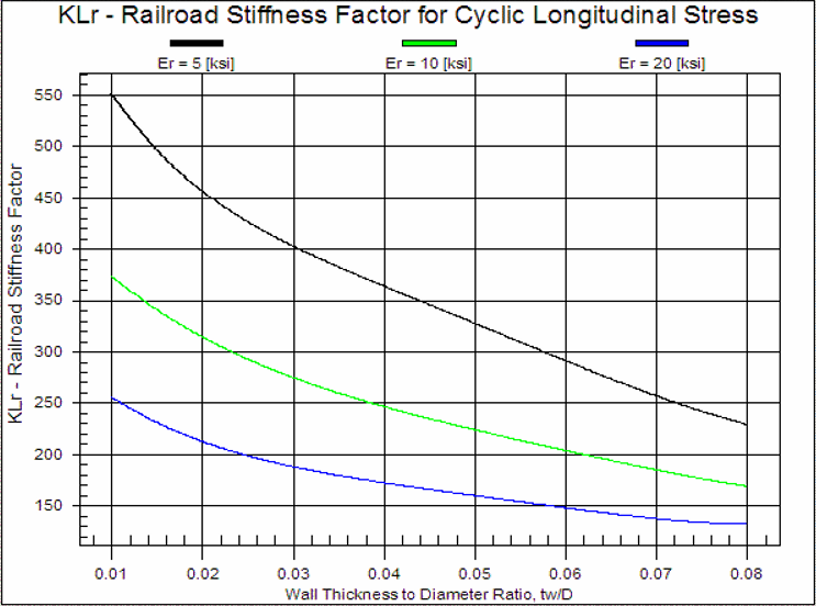
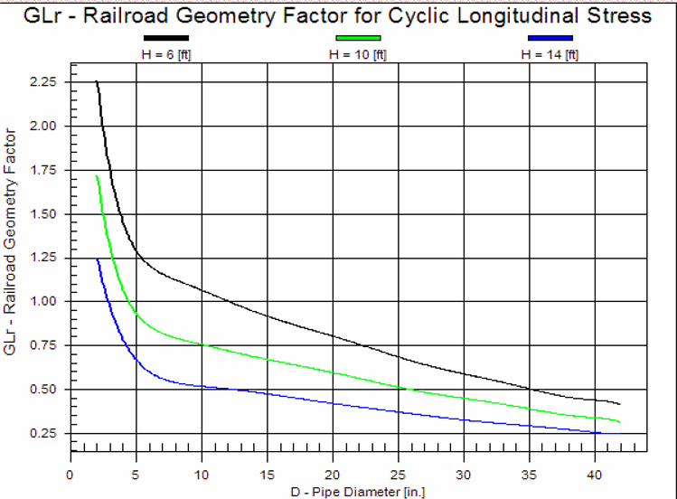
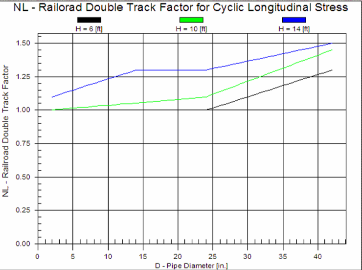
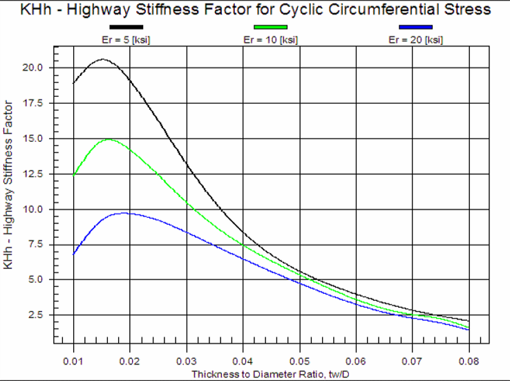
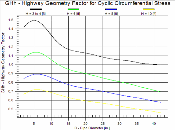
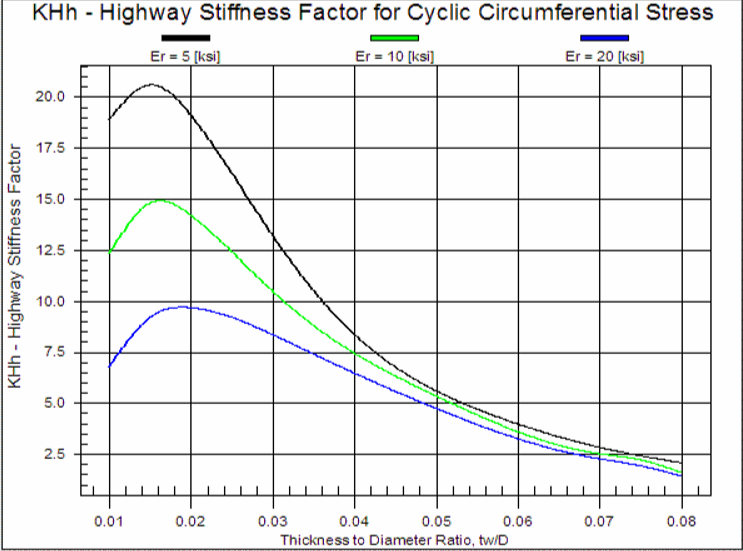
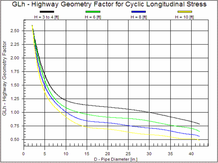
- APPENDIX A
API 1102 Design Curves
Related Links
Table of Contents
Table of Pages
- Pipeline HUB User Resources
- AC Mitigation PowerTool
- API Inspector's Toolbox
- Crossings Workflow
- Horizontal Directional Drilling PowerTool
- Hydrotest PowerTool
- Pipeline Toolbox
- PRCI AC Mitigation Toolbox
- PRCI RSTRENG
- RSTRENG+
- Ad-hoc Analysis
- Database Import
- Data Availability Dashboard
- ESRI Map
- Report Builder
- Crossings Workflow
- Hydrotest PowerTool
- Investigative Dig PowerTool
- Hydraulics PowerTool
- External Corrosion Direct Assessment Procedure - RSTRENG
- Canvas
- Definitions