
API 1102: Pipeline Crossing Highway
Introduction
API 1102 – PC PISCES (Personal Computer Pipeline Soil Crossing Evaluation System) program is based on the design methodology resulting from the research and has been implemented in the program to aid pipeline designers in analyzing existing uncased pipelines and designing new uncased pipelines that cross beneath highways. The details of the full design methodology can be found in “Technical Summary and Database for Guidelines for Pipelines Crossing Beneath Highways” (GRI0285, Final Report) and should be read and understood.
The design methodology used in program follows directly the approach given in API RP 1102. Concise summaries of the Cornell/GRI Guidelines are given in “Guidelines for Pipelines Crossing Beneath Highways” (Stewart, et al., 1991b). API RP 1102 should be available to the user for additional documentation and preferences, and supplement the information provided by the program help and graphical display of the design curves.
This design methodology relates to:
- Steel pipelines installed using trenchless construction methods, in particular auger boring, with the crossing perpendicular to the railroad.
- Pipelines having diameters 2 to 42 inches (51 to 1067 mm) can be analyzed.
- The wall thickness to diameter ratios must be within the range of tw/D = 0.01 to 0.08.
- Highway crossings can be analyzed for depths of cover of:
- 4 to 10 feet (in accordance with API 1102)
- 3 to 10 ft (PC-PISCES)
- Highway loadings are based on both single and tandem-axle truck loading configurations.
Variables and Boundary Conditions
Pipe Properties
DIAMETER.
- The diameter, D, is the outside pipe diameter, and has units of inches.
- The range of D is 2.0000 to 42.000 in. The default value is D = 12.750 in.
MAXIMUM ALLOWABLE OPERATING PRESSURE, (MAOP).
- The maximum allowable operating pressure, MAOP, is used as the design internal pressure for calculating circumferential stress due to internal pressurization, and has units of psi.
- The range for MAOP is 0000 to 5000 psig.
SPECIFIED MINIMUM YIELD STRENGTH, (SMYS).
- The specified minimum yield strength, SMYS, has a range of allowable values covering steel grades A25 (SMYS = 25000 psi) to X-80 (SMYS = 80000 psi).
- The SMYS is also used to establish the girth and longitudinal weld fatigue endurance limits.
DESIGN FACTOR, (F).
- Although 49 CFR 192 or 195, establishes a design factor, F, the user can input another F value.
- The range for F is from 0.10 to 1.00. The default design factor is F = 0.72.
LONGITUDINAL JOINT FACTOR, (E).
- The longitudinal joint factor, E, depends on the type of pipe welds.
- The input screen limits E to either 0.60, 0.80, or 1.00, consistent with the values given in 49CFR192, Section 192.113.
- The default value is E = 1.00.
INSTALLATION TEMPERATURE, (T1).
- The installation temperature, T1 is given in F.
- This value is used with T2 to determine thermal stress effects.
- The range of T1 is from -20 to 450 F.
OPERATING TEMPERATURE, (T2).
- The operating temperature, T2 is give in F.
- The T2 value is used to determine the temperature derating factor, T.
- T2 also is used with T1 to determine thermal stress effects.
- The range for T2 is from -20 to 450 F.
WALL THICKNESS, (wt.).
- The pipe wall thickness, wt. has units of inches.
- The wall thickness to diameter ratios must be within the range of wt./D = 0.01 to 0.08.
DEPTH OF CARRIER PIPE, (H).
- The depth of the carrier pipe, H, given it ft, is measured from the top of tie to the pipeline crown for railroads and from the top of pavement to the pipeline crown for highways.
- The limits on H are: 6ft <= H <= 14 ft for railroads, and 4ft <= H <= 10 ft for highways (API 1102); 3ft <= H <= 10 ft for highways (PC-PISCES) These are the depth limits for the live load design curves.
- The depth, H, also is used to establish the impact factor, Fi used in the design methodology.
BORED DIAMETER, (Bd).
- The bored diameter, Bd (Bd in RP 1102), has units of inches.
- The minimum value is Bd = D, and the maximum value is Bd = D + 6 in. The default value is Bd = D + 2 in.
SOIL TYPE FOR THE EARTH LOAD
- The soil type for the earth load calculations is either A or B.
- See Figure 4 in API RP 1102.
MODULUS OF SOIL REACTION. (E’).
- The modulus of soil reaction, E’, has units of ksi.
- The minimum value allowed is E = 0.2 ksi, and the maximum recommended value for auger bored installations is E = 2.0 ksi.
- The maximum input value for E is 8.0 ksi. When an E value greater than 2.0 ksi is used, a warning will be displayed that the value is beyond the normal range of E’ for auger bored installations.
- See details in API RP 1102.
SOIL RESILIENT MODULUS, (Er).
- The soil resilient modulus, Er has units of ksi.
- The minimum allowable value is Er = 5.00 ksi, and the maximum allowable value is Er = 20.0 ksi.
- These are the limits for the live load design curves.
- See Table 3 in API RP 1102 or the default value is Er = 10.0 ksi, as recommended in API RP 1102.
SOIL UNIT WEIGHT, ®.
- The soil unit weight, r, has units of pcf, and can range from 0 to 150 pcf.
- The default value is r = 120 pcf.
TYPE OF LONGITUDINAL WELD
- The type of longitudinal weld is used with the SMYS to establish the longitudinal weld fatigue endurance limit, SFL.
- The choices for the type of longitudinal seam weld are SAW or ERW.
- See Table 3 in API RP 1102 for the influence of longitudinal weld type and SMYS on the seam weld fatigue endurance limits.
- The default type of longitudinal weld is SAW.
DESIGN SINGLE WHEEL LOAD, Ps (HIGHWAY ONLY)
- The design single wheel load, Ps , has units of kips, and can range from 0.00 to 20.0 kips.
- The pavement type, design wheel loads, diameter, and depth are used to establish the pavement type factor, R, and axle configuration factor, L.
- The default value is Ps = 12.0 kips, as recommended in API RP 1102.
DESIGN TANDEM WHEEL LOAD, Pt (HIGHWAY ONLY)
- The design tandem wheel load, Pt (, has units of kips, and can range from 0.00 to 20.0 kips.
- The pavement type, design wheel loads, diameter, and depth are used to establish the pavement type factor, R, and axle configuration factor, L.
- The default value is Ps = 10.0 kips, as recommended in API RP 1102.
PAVEMENT TYPE (HIGHWAY ONLY)
- The pavement type for highway crossings can be either flexible, none, or rigid.
- The pavement type, design wheel loads, diameter and depth are used to establish the pavement type factor, R, and axle configuration factor, L.
- The default pavement type is flexible.
YOUNGS MODULUS
- Es Young’s modulus of the steel carrier pipe, Es (Es in RP 1102), has units of ksi.
- The range is from 29 000 to 31 000 ksi. The default value is Es = 30 000 ksi.
POSSIONS RATIO
- Possion’s ratio of the steel carrier pipe, s, is used to assess thermal and longitudinal stresses due to the circumferential earth load and internal pressure stresses.
- The allowable range is from 0.25 to 0.30. The default value is s = 0.30.
COEFFICIENT OF THERMAL EXPANSION, (T).
- The coefficient of thermal expansion of the steel carrier pipe T, is given for temperature is F, and is used to assess longitudinal thermal stresses.
- The range is from 0.0000060 to 0.0000080 per F.
- The default value is T = 0.0000065 per F.
Workflow
Step 1: Check wall thickness for the operation pressure. To continue wt > wtd
- wtd – Wall Thickness Minimum [in]
- wt – Wall Thickness Actual [in]
- D – Pipe Diameter [in]
- S – Specified Minimum Yield Strength [psi]
- P – Design Pressure [psi]
- F – Design Factor
- E – Longitudinal Joint Factor
- T – Temperature Derating Factor
Step 2: Check Allowable Barlow Stress
(see External Link: Barlow’s Formula in Wikipedia.com)
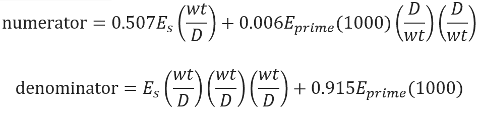
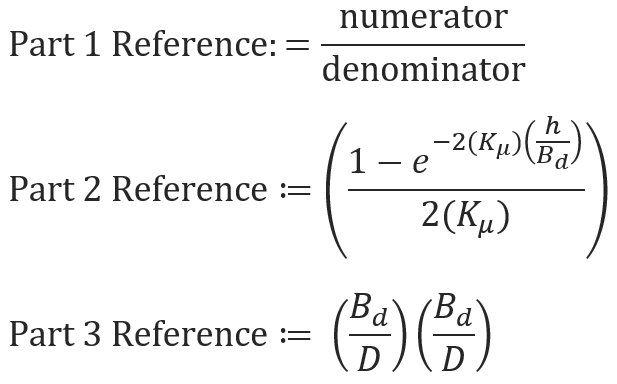
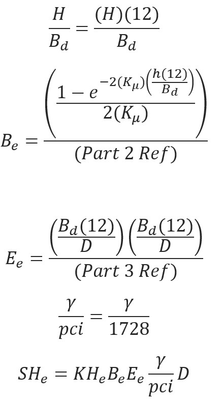
Step 3: Circumferential stress due to Earth Load
Soil type – Default Value: (Kμ= 0.165 for Soil Type A, Kμ= 0.192 for Soil Type B)
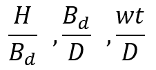
𝐻 − Pipe Depth[ft]
𝐵𝑑 − Bored Diameter[in]
𝐸𝑝𝑟𝑖𝑚𝑒 − Modulus of Soil Reaction
𝐸𝑟 − Resilient Module
𝛾 − Average unit weight of soil
𝐸𝑠 − Young′s Modulus of Elasticity
![]()
Step 4: Impact Factor and Applied Design Surface Pressure(F-Flexible, R-Rigid, N-None) (Case 1,2,3)
Determine the Critical Load case and the applied surface design load. Find these values from Table Impact Factor:
If Depth of Cover ≤ 5ft,1.5, = (1.5 – 0.03)(Cover-5)
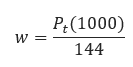
Tandem Axle:
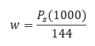
Single Axle:
Where
𝑃𝑡 − Design Wheel Load from Tandem Axis[kpsi]
𝑃𝑠 − Design Wheel Load from Single Axis[kpsi]
𝑤 − Critical Load[kpsi]
Step 5: Cyclic Stress, 𝑫𝑺𝑯𝒉 & 𝑫𝑺𝑳𝒉
Reference the Design Curves in Appendix A from “Technical Summary and Database for Guidelines for Pipelines Crossing Beneath Railroads and Highways” (GRI-91/0285, Final Report).
𝐾𝐻ℎ − Highway Stiffness Factor for Cyclic Circumferential Stress
𝐺𝐻ℎ − Highway Geometry Factor for Cyclic Circumferential Stress
𝐷𝑆𝐻ℎ − Cyclic Circumferential Stress
𝐾𝐿ℎ − Highway Stiffness Factor for Cyclic Longitudinal Stress
𝐺𝐿ℎ − Highway Geometry Factor for Cyclic Longitudinal Stress
𝐷𝑆𝐿ℎ − Cyclic Longitudinal Stress
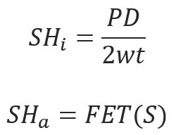
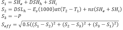
Step 6: Circumferential Stress due to Internal Pressurization Shi
Step 7: Principle Stresses 𝑺𝟏,𝑺𝟐,𝑺𝟑
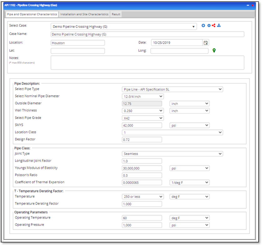
Input Parameters
- To create a new case, click the “Add Case” button
- Select the API 1102 Gas Pipeline Crossing – Highway application from the Pipeline Crossing module.
- Enter Case Name, Location, Date and any necessary notes.
- Fill out all required fields.
- Make sure the values you are inputting are in the correct units.
- Click the CALCULATE button.
- Pipe Type
- Nominal Pipe Size(in):(0.625” – 48”)
- Pipe Outside Diameter(in):(0.625” – 48”)
- Pipe Wall Thickness(in):(0.625” >2”)
- Young’s Modulus of Elasticity:(29000000psi – 30000000psi)
- Poisson’s Ratio (-1 – 0.5)
- Thermal Expansion Coefficient(1/°F) :(0.0000022in/inF – 0.000012in/inF)
- Joint Type
- Location Class: Refer 49 CFR 192.5
- Temperature Derating Factor
- Operating Pressure
- Operating Temperature
- Specified Minimum Yield Stress:(24000psi-80000psi)
- Design Factor: Reference 49 CFR 192.611
- Longitudinal Joint Factor
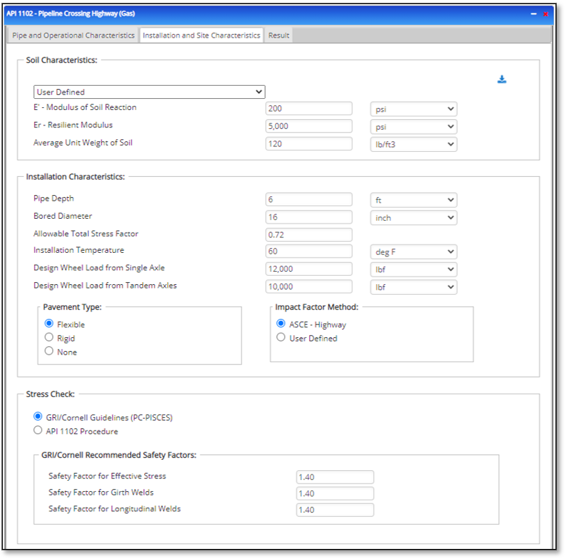
- Modulus of Soil Reaction
- Resilient Modulus
- Average unit weight of Soil:(70lb/ft3 – 150lb/ft3)
- Pipe Depth
- Bored Diameter
- Installation Temperature
- Design Wheel Load From Single Axis
- Design Wheel Load From Tandem Axis
- Pavement Type
- Impact Factor Method
- Fi
- Safety Factor for Effective Stress
- Safety Factor for Girth Welds
- Safety Factor for Longitudinal Welds
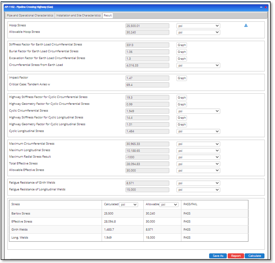
Outputs/Reports
- View the results.
- If an input parameter needs to be edited be sure to hit the CALCULATE button after the change.
- To SAVE, fill out all required case details then click the SAVE button.
- To rename an existing file, click the SAVE As button. Provide all case info then click SAVE.
- To generate a REPORT, click the REPORT button.
- The user may export the Case/Report by clicking the Export to Excel/PowerPoint icon.
- To delete a case, click the DELETE icon near the top of the widget.
- Hoop Stress
- Allowable Hoop Stress
- Stiffness Factor for Earth Load Circumferential Stress
- Burial Factor for Earth Load Circumferential Stress
- Excavation Factor for Earth Load Circumferential Stress
- Circumferential Stress from Earth Load
- Impact Factor
- Highway Stiffness Factor for Cyclic Circumferential Stress
- Highway Geometry Factor for Cyclic Circumferential Stress
- Cyclic Circumferential Stress
- Highway Stiffness Factor for Cyclic Longitudinal Stress
- Highway Geometry Factor for Cyclic Longitudinal Stress
- Cyclic Longitudinal Stress
- Maximum Circumferential Stress
- Maximum Longitudinal Stress
- Maximum Radial Stress
- Total Effective Stress
- Allowable Effective Stress
- Fatigue Resistance of Girth Welds
- Fatigue Resistance of Longitudinal Welds
- Barlow Stress
- Effective Stress
- Girth Welds
- Long Welds
Tutorial Videos
- Finding Road Crossings (2 min 52 sec)
- Crossings Workflow Demo (4 min 50 sec)
Related Links
Table of Contents
Table of Pages
Table of Contents
- Pipeline HUB User Resources
- AC Mitigation PowerTool
- API Inspector's Toolbox
- Horizontal Directional Drilling PowerTool
- Crossings Workflow
- Hydrotest PowerTool
- Pipeline Toolbox
- Encroachment Manager
- PRCI AC Mitigation Toolbox
- PRCI RSTRENG
- RSTRENG+
- Ad-hoc Analysis
- Database Import
- Data Availability Dashboard
- ESRI Map
- Report Builder
- Crossings Workflow
- Hydrotest PowerTool
- Investigative Dig PowerTool
- Hydraulics PowerTool
- External Corrosion Direct Assessment Procedure - RSTRENG
- Canvas
- Definitions
- Pipe Schedule and Specifications Tables