
Design Pressure – Steel Pipe
Design pressure for steel pipe is calculated using Barlow’s Equation. The design pressure for steel pipe is determined in accordance with the following formula:
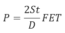
P = Design pressure in pounds per square inch (kPa) gage.
S = yield strength in pounds per square inch (kPa) determined in accordance with 192.107.
D = Nominal outside diameter of the pipe in inches (millimeters).
t = Nominal wall thickness of the pipe in inches (millimeters). If this is unknown, it is determined in accordance with 192.109. Additional wall thickness required for concurrent external loads in accordance with 192.103 may not be included in computing design pressure.
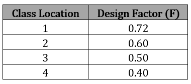
F = Design factor determined in accordance with 192.111.
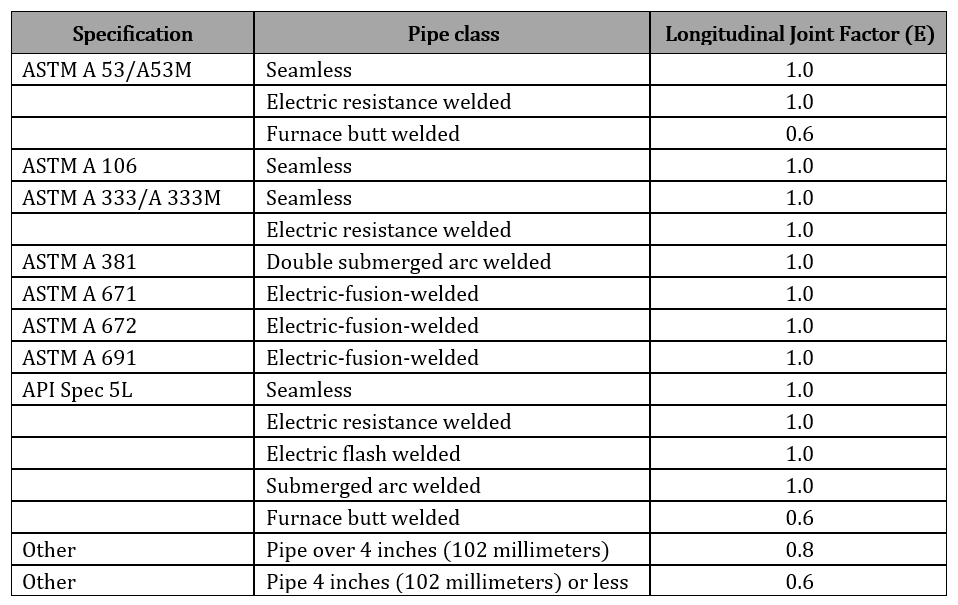
E = Longitudinal joint factor determined in accordance with 192.113.
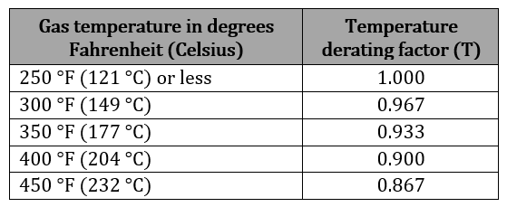
T = temperature derating factor determined in accordance with 192.115
Class Location and Design factor (F) for steel pipe
Longitudinal joint factor (E) for steel pipe Table
Temperature derating factor (T) for steel pipe Table
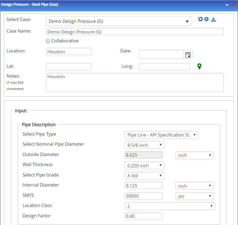
Input Parameters
- Select the Design Pressure – Steel Pipe application from the Steel Pipe – Design and Stress Analysis module.
- To create a new case, click the “+” button
- Enter Case Name, Location, Date and any necessary notes.
- Fill out all required fields.
- Make sure the values you are inputting are in the correct units.
- Click the CALCULATE button.
- Nominal Pipe Size(in):(0.625” – 48”)
- Wall Thickness(in):(0.068”- >2”)
- Pipe grade:(24000psi-80000psi) (if unknown use Grade A 24000)
- Design Factor: Reference 49 CFR 192.611
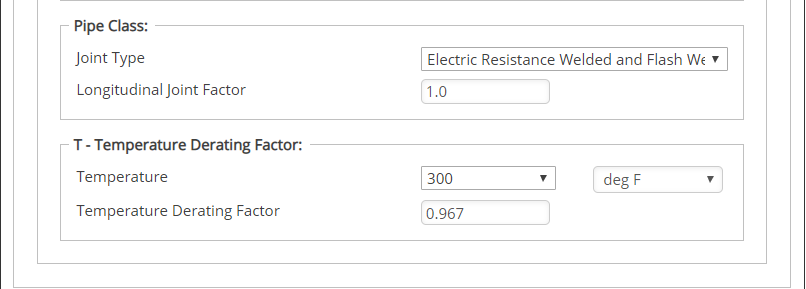
- E – Longitudinal Joint Factor
- T – Temperature Derating Factor(°F).
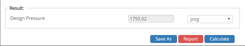
Outputs/Reports
- View the results.
- If an input parameter needs to be edited be sure to hit the CALCULATE button after the change.
- To SAVE, fill out all required case details then click the SAVE button.
- To rename an existing file, click the SAVE As button. Provide all case info then click SAVE.
- To generate a REPORT, click the REPORT button.
- The user may export the Case/Report by clicking the Export to Excel/PowerPoint icon.
- To delete a case, click the DELETE icon near the top of the widget.
- The single output this calculation provides is Design Pressure in(psi).
Related Links
Table of Contents
Table of Pages
Table of Contents
- Pipeline HUB User Resources
- AC Mitigation PowerTool
- API Inspector's Toolbox
- Horizontal Directional Drilling PowerTool
- Crossings Workflow
- Hydrotest PowerTool
- Pipeline Toolbox
- Encroachment Manager
- PRCI AC Mitigation Toolbox
- PRCI RSTRENG
- RSTRENG+
- Ad-hoc Analysis
- Database Import
- Data Availability Dashboard
- ESRI Map
- Report Builder
- Crossings Workflow
- Hydrotest PowerTool
- Investigative Dig PowerTool
- Hydraulics PowerTool
- External Corrosion Direct Assessment Procedure - RSTRENG
- Canvas
- Definitions
- Pipe Schedule and Specifications Tables