The buoyancy of a pipeline depends upon the weight of the pipe, the weight of the volume of water displaced by the pipe, the weight of the liquid load carried by the pipe and the weight of the backfill. As a conservative analytical practice, consider the pipeline empty for two reasons; so, the weight of the liquid will be considered as an additional safety factor and the possibility of the pipeline not being in use during a period.
This calculation is used to determine the buoyance of the specified underwater pipe based on the required thickness of concrete coating to counter the buoyancy forces.
The calculation does not account/allow for depth of water or burial. PLTB input is unit weight of water.
Determine bare pipe weight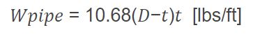
Where:
𝐷 − Pipe outside diameter(in)
𝑡 − Pipe wall thickness(in)
Determine total volume of pipe in air including corrosion and concrete coating
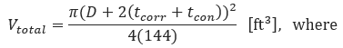
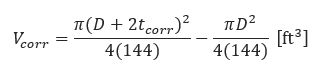
𝑡𝑐𝑜𝑟𝑟 = Corrosion coating thickness(in)
𝑡𝑐𝑜𝑛 = Concrete coating thickness(in)
Determine volume of corrosion coating
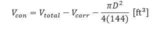
Determine volume of concrete coating
Determine total weight of pipe in air, including weight of corrosion and concrete coating
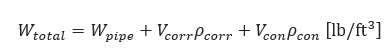
𝜌𝑐𝑜𝑟𝑟 = Corrosion coating specific weight(lb/ft3)
𝜌𝑐𝑜𝑛 = Concrete coating specific weight(lb/ft3)
Determine weight of displaced water
𝜌𝑤 = 𝑆pecific weight of water(lb/ft3)
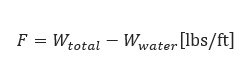
Determine the difference
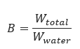
Determine bulk specific gravity
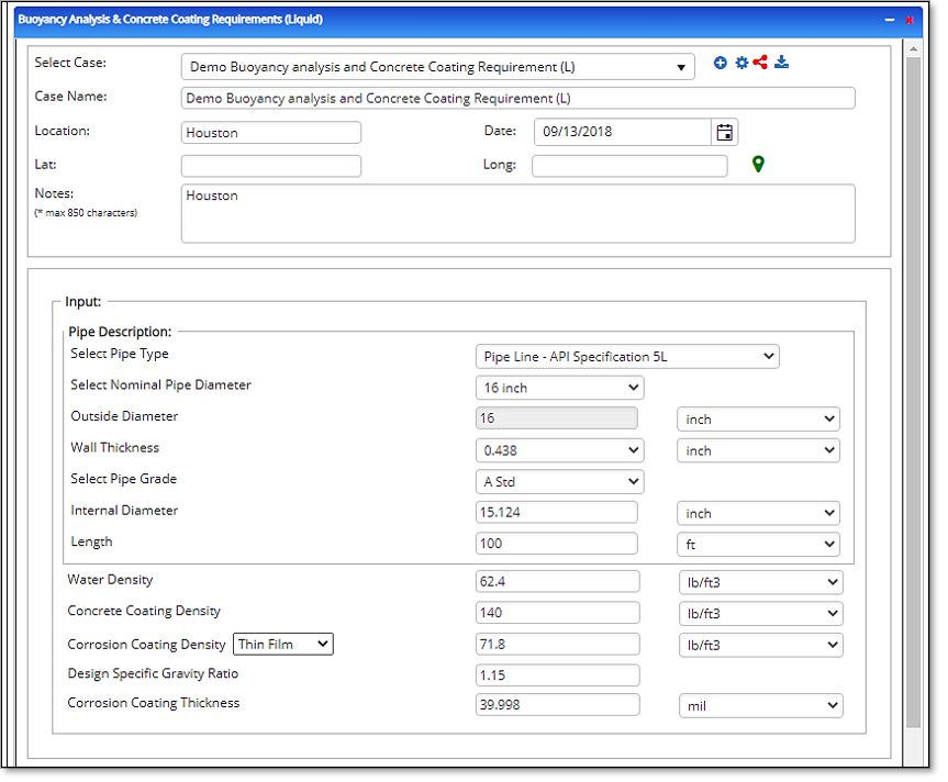
Input Parameters
- To create a new case, click the “Add Case” button
- Select the Buoyancy Analysis & Concrete Coating Requirements application from the Steel Pipe
- Design and Stress Analysis module.
- Enter Case Name, Location, Date and any necessary notes.
- Fill out all required fields.
- Make sure the values you are inputting are in the correct units.
- Click the CALCULATE button.
- Nominal Pipe Size(in)
- Wall Thickness(in)
- Corrosion Coating Thickness(in)
- Pipe length(ft/joint). Given values consist of Water Density(lbs./ft³)
- Corrosion Coating Density(lbs./ft³)
- Concrete Coating Density(lbs./ft³)
- Design Specific Gravity Ratio
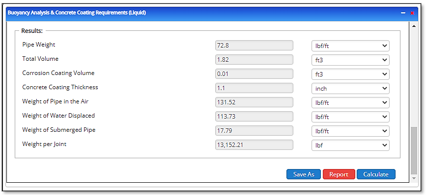
Outputs/Reports
- View the results.
- If an input parameter needs to be edited be sure to hit the CALCULATE button after the change.
- To SAVE, fill out all required case details then click the SAVE button.
- To rename an existing file, click the SAVE As button. Provide all case info then click SAVE.
- To generate a REPORT, click the REPORT button.
- The user may export the Case/Report by clicking the Export to Excel/PowerPoint icon.
- To delete a case, click the DELETE icon near the top of the widget.
- Pipe weight(lbs./ft)
- Total Volume(ft³)
- Corrosion Coating Volume(ft³)
- Concrete Coating Thickness(in)
- Weight of Pipe in Air(lbs./ft)
- Weight of Water Displaced(lbs./ft)
- Weight of Submerged Pipe(lbs./ft)
- Weight per Joint(lbs./ft).