
Pipeline Facilities
Introduction
The Pipeline Toolbox is home to many tools and calculators. The PLTB User’s Guide presents information, guidelines and procedures for use during design, and construction tasks for field or office applications.
In today’s competitive and changing environment, it is crucial that pipelines and associated facilities create and sustain value for their stakeholders. This value can only be achieved by incorporating dependability into the pipeline system, in whole or in part. Dependability characteristics address not just availability and reliability as the probability of successful performance, but also identify other potential risk exposures such as degradation and wear out that advocate the need for maintenance and logistic support to sustain “problem free” pipeline and facility operation. The following module contains a few calculations that can address some areas and tasks conducted on facilities to ensure greater levels of safety and operation.
Erosional and Sonic Velocity has been added to the following Modules and Calculations.
- Hot Tap Sizing
Erosional Velocity
Pipe erosion begins when velocity exceeds the value of C/SQRT(ρ) in ft/sec, where ρ = gas density (in lb./ft3) and C = empirical constant (in lb/s/ft2) (starting erosional velocity). We used C=100 as API RP 14E (1984). However, this value can be changed based on the internal conditions of the pipeline. The following equation is used for the calculation.
Inputs
- C – Factor (dimensionless)
- Compressibility Factor (dimensionless)
- Gas Gravity (dimensionless)
- Operating Pressure (psig)
- Operating Temperature (deg F)
Erosional Velocity is in ft/sec.
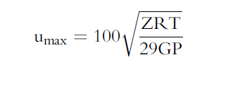
Sonic Velocity
The maximum possible velocity of compressible fluid gas/liquids in pipe is called sonic velocity.
Inputs
- K = Cp/Cv – the ratio of specific heats at constant pressure to constant volume (fluid directive)
- G=32.2 ft/sec
- R=1544/mol. Wt.
- T = Absolute temperature in deg R
K = A + B(P) – C(T) 1/2 – D(API) – E(API)2 + F(T)(API)
Sonic Velocity is in ft/sec.
Module Application
- Hot Tap Sizing
- Relief Valve Sizing For Gas or Vapor
- Relief Valve: Reactive Force
- Reinforcement of Welded Branch Connection
References
-
ASME – Boiler and Pressure Vessel Code, Section VIII
-
API – RP 520 Part 2
-
ASME B31.8 Gas Transmission and Distribution Piping Systems
-
ASME B31.3, B31.4 and B31.8 – Full Encirclement Sleeves (See Appendices)
Appendix
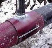
Even though Technical Toolboxes does not provide software for a full-encirclement reinforcing saddle, many operators use them to provide reinforcement for branch outlets in accordance with ASME B31.3, B31.4, B31.8, and other applicable design codes. Full-encirclement reinforcing saddles are designed to fully encircle the run pipe, however; they are not designed to be pressure-retaining devices. To avoid gas entrapment during welding and to prevent pressure containment, should a leak develop underneath the saddles; these saddles should be provided with a vent to allow escaping product.
A typical field applied Full Encirclement Reinforcement Weldment Saddle is shown below:

Related Links
Table of Contents
Table of Pages
Table of Contents
- Pipeline HUB User Resources
- AC Mitigation PowerTool
- API Inspector's Toolbox
- Horizontal Directional Drilling PowerTool
- Crossings Workflow
- Hydrotest PowerTool
- Pipeline Toolbox
- Encroachment Manager
- PRCI AC Mitigation Toolbox
- PRCI RSTRENG
- RSTRENG+
- Ad-hoc Analysis
- Database Import
- Data Availability Dashboard
- ESRI Map
- Report Builder
- Crossings Workflow
- Hydrotest PowerTool
- Investigative Dig PowerTool
- Hydraulics PowerTool
- External Corrosion Direct Assessment Procedure - RSTRENG
- Canvas
- Definitions
- Pipe Schedule and Specifications Tables